Slew Rate Limiting
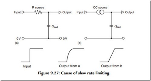
This is a potential problem that can occur in any voltage amplifier or other signal handling stage in which an element of load capacitance (which could simply be circuit stray capacitance) is associated with a drive circuit whose output current has a finite limit. The effect of this is shown in Figure 9.27. If an input step waveform is applied to network (a), then the output signal will have a waveform of the kind shown at ‘a’, and the slope of the curve will reflect the potential difference that exists, at any given moment, between the input and the output. Any other signal that is present at the same time will pass through this network, from input to output, and only the high-frequency components will be attenuated.
However, if the drive current is limited, the output waveform from circuit 9.27 (b) will be as shown at ‘b’ and the slope of the output ramp will be determined only by the current limit imposed by the source and the value of the load capacitance. This means that any other signal component that is present, at the time the circuit is driven into slew rate limiting, will be lost. This effect is noticeable, if it occurs, in any high-quality audio system and gives rise to a somewhat blurred sound—a defect that can be lessened or removed if the causes (such as too low a level of operating current for some amplifying stage) are remedied. It is prudent, therefore, for the amplifier designer to establish the possible voltage slew rates for the various stages in any new design and then to ensure
that the amplifier does not receive any input signal that requires rates of change greater than the level that can be handled. A simple input integrating network of the kind shown in Figure 9.27(a) will often suffice.
