Mechanical strain
The words stress and strain are often confused in everyday life, and a clear definition is essential at this point. Strain is the result of stress, and is defined as the fractional change of the dimensions of an object. By fractional change, I mean that the change of dimension is divided by the original dimension, so that in terms of length, for example, the strain is the change of length divided by the original length. This is a quantity that is a pure number, one length divided by another, having no physical dimensions. Strain can be defined for area or for volume measurements in a similar way as change divided by original quantity. For example, area strain is change of area divided by original area, and volume strain is change of volume divided by original volume.
A stress, by contrast, is a force divided by an area. As applied to a wire or a bar in tension or compression, for example, the tensile (pulling) stress is the applied force divided by the area over which it is applied, which will be the area of cross section of the wire or bar. For materials such as liquids or gases which can be compressed uniformly in all dimensions, the bulk stress is the force per unit area, which is identical to the pressure applied, and the strain is the change of volume divided by the original volume. The most common strain transducers are for tensile mechanical strain. The measurement of strain allows the amount of stress to be calculated through a knowledge of the elastic modulus. The definition of any type of elastic modulus is stress/ strain (which has the units of stress, since strain has no physical units), and the most commonly used elastic moduli are the linear Young’s modulus, the shear (twisting) modulus, and the (pressure) bulk modulus.
For small amounts of strain, the strain is proportional to stress, and an elastic modulus is a quantity that expresses the ratio stress/strain in the
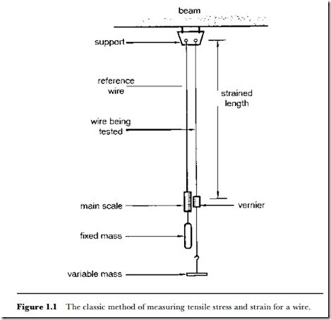
elastic region, i.e. the portion of the stress-strain graph that is linear. For example, Young’s modulus is the ratio tensile stress/tensile strain, typically measured for a material in the form of a wire (Figure 1.1). The classic form of measurement, still used in school demonstrations, uses a long pair of wires, one loaded, the other carrying a vernier scale.
Sensing tensile strain involves the measurement of very small changes of length of a sample. This is complicated by the effect of changes of temperature, which produce expansion or contraction. For the changes of around 0-30oC that we encounter in atmospheric temperature, the expansion or
contraction of length will be about the same size as the changes caused by large amounts of stress. Any system for sensing and measuring strain must therefore be designed in such a way that temperature effects can be compensated for. The principles used to sense linear or area strain are piezoresistive and piezoelectric.
The commonest form of strain measurement uses resistive strain gauges.
A resistive strain gauge consists of a conducting material in the form of a
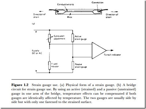
thin wire or strip which is attached firmly to the material in which strain is to be detected. This material might be the wall of a building, a turbine blade, part of a bridge, anything in which excessive stress could signal impending trouble. The fastening of the resistive material is usually by means of epoxy resins (such as ‘Araldite’), since these materials are extremely strong and are electrical insulators. The strain gauge strip will then be connected as part of a resistance bridge circuit (Figure 1.2). This is an example of the piezoresistive principle, because the change of resistance is due to the deformation of the crystal structure of the material used for sensing.
The effects of temperature can be minimized by using another identical unstrained strain gauge in the bridge as a comparison. This is necessary not only because the material under investigation will change dimensions as a result of temperature changes, but because the resistance of the strain gauge element itself will vary. By using two identical gauges, one unstrained, in the bridge circuit, these changes can be balanced against each other, leaving only the change that is due to strain. The sensitivity of this type of gauge, often called the piezoresistive gauge, is measured in terms of the gauge factor. This is defined as the fractional change of resistance divided by the change of strain, and is typically about 2 for a metal wire gauge and about 100 for a semiconductor type.
The change of resistance of a gauge constructed using conventional wire elements (typically thin Nichrome wire) will be very small, as the gauge factor figures above indicate. Since the resistance of a wire is proportional to its length, the fractional change of resistance will be equal to the fractional change of length, so that changes of less than 0.1% need to be detected. Since the resistance of the wire element is small, i.e., of the order of an ohm or less, the actual change of resistance is likely to be very small compared to the resistance of connections in the circuit, and this can make measurements very uncertain when small strains have to be measured.
The use of a semiconductor strip in place of a metal wire makes measurement much easier, because the resistance of such a strip can be considerably greater, and so the changes in resistance can be correspondingly greater. Except for applications in which the temperature of the element is high (for example, gas-turbine blades), the semiconductor type of strain gauge is preferred. Fastening is as for the metal type, and the semiconductor material is surface passivated protected from atmospheric contamination by a layer of oxidation on the surface. This latter point can be important, because if the atmosphere around the gauge element removes the oxide layer, then the readings of the gauge will be affected by chemical factors as well as by strain, and measurements will no longer be reliable.
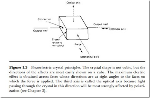
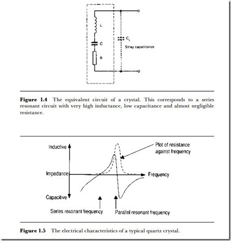
Piezoelectric strain gauges are useful where the strain is of short duration, or rapidly changing in value. A piezoelectric material is a crystal whose ions move in an asymmetrical way when the crystal is strained, so that an EMF is generated between two faces of the crystal (Figure 1.3). The EMF can be very large, of the order of several kV for a heavily strained crystal,
so that the gauge can be sensitive, but the output impedance is very high and usually capacitive. Figure 1.4 illustrates the electrical equivalent circuit, and Figure 1.5 shows the response around the main resonant frequencies for a quartz crystal. The output of a piezoelectric strain gauge is not DC, so this type of gauge is not useful for detecting slow changes, and its main application is for acceleration sensing (see Chapter 2).
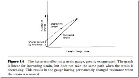
Two major problems of strain gauge elements of any type are hysteresis and creep. Hysteresis means that a graph of resistance change plotted against length change does not follow the same path of decreasing stress as for increasing stress (Figure 1.6). Unless the gauge is over-stretched, this effect should be small, of the order of 0.025% of normal readings at the
most. Overstretching of a strain gauge will cause a large increase in hysteresis, and, if excessive, will cause the gauge to show a permanent change of length, making it useless until it can be recalibrated. The other problem, creep, refers to a gradual change in the length of the gauge element which does not correspond to any change of strain in the material that is being measured. This also should be very small, of the order of 0.025% of normal readings. Both hysteresis and creep are non-linear effects which can never be eliminated but which can be reduced by careful choice of the strain gauge element material. Both hysteresis and creep increase noticeably as the operating temperature of the gauge is raised.
LOAD CELLS
Load cells are used in electronic weighing systems. A load cell is a force transducer that converts force or weight into an electrical signal. Basically, the load cell uses a set of strain gauges, usually four connected as a V\heat- stone-bridge circuit. The output of the bridge circuit is a voltage that is proportional to the force on the load cell. This output can be processed directly, or digitized for processing.
