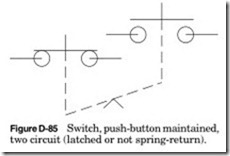
Switch, push-button
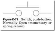
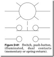
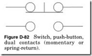
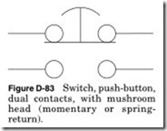
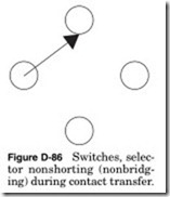
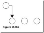
Push buttons come in all shapes and sizes. There are only three types: Normally Open, Normally Closed, or a combination of contacts or illumi- nated. Most push buttons allow you to change the state of the contacts in the field. Many allow you to add contacts in the field, allowing for a large number of contacts either Open or Closed.
This table shows the state of each contact in Fig. D-87 in each position. A table like this will typically be in the Notes section of the drawing or as part of the specifications. If the selector or switch is programmed by the manufacturer, then it will be as an attachment to the specifications.
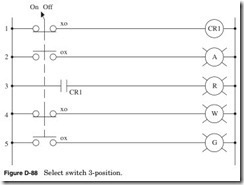
The positions of the contacts can also be shown on a drawing like Fig. D-88 using Xs and Os. The X indicates contact closed and O indi- cates an open contact. The position of the X or O is the position of the switch, etc., A, B, C, or, if numbered, 1, 2, 3.
Line 1 If the switch is in position A, then according to the XOO next to the switch contact, the relay CR1 will be energized. If it is in position B or C, then the relay CR1 will be deenergized.
Line 2 If the switch is in position B, then according to the OXO next to the switch contact, the amber pilot light will be illuminated.
If it is in position A or C, then the amber pilot light will not be illu- minated.
Line 3 If the relay CR1 is energized, then the Normally Open CR1 is closed and the red pilot light will be illuminated.
Line 4 If the switch is in position C, then according to the OOX next to the switch contact, the white pilot light will be illuminated. If it is in position A or B, then the white pilot light will not be illuminated.
Line 5 If the switch is in position B, then according to the OXO next to the switch contact, the green pilot light will be illuminated. If it is in position A or C, then the green pilot light will not be illuminated.
Speed switch
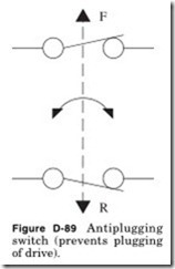
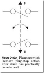
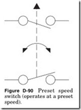
Operated by shaft rotation; F = forward, R = reverse.
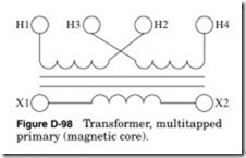
In Fig. D-98, connect H3 to H2 for 220 to 110 V. For an isolation trans- former connect H3 to H1 and H2 to H4 for 110-V input to 110-V output. Always check the nameplate on the transformer to make sure that is the correct voltage.
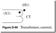
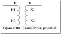
When I the polarity mark is shown (•). It indicates the instantaneous direction of the current into one polarity mark which corresponds to the current out of the other polarity mark.
Care should be taken with the secondary of the current transformer. The secondary should not be disconnected from the load while current is flowing. The transformer will attempt to continue driving current across the effectively infinite impedance. This will produce a high volt- age across the secondary, which can be in the range of several kilovolts and can cause arcing. This voltage will compromise your safety and permanently affect the accuracy of the transformer.
When I the polarity mark is shown (•). It indicates the instantaneous direction of the current.


![Figure-D-87-Switch-selector-push-but[2] Figure-D-87-Switch-selector-push-but[2]](http://machineryequipmentonline.com/electric-equipment/wp-content/uploads/2020/06/Figure-D-87-Switch-selector-push-but2_thumb.jpg)




![Figure-D-102-Wound-rotor-induction-m[1] Figure-D-102-Wound-rotor-induction-m[1]](http://machineryequipmentonline.com/electric-equipment/wp-content/uploads/2020/06/Figure-D-102-Wound-rotor-induction-m1_thumb.jpg)