Alternating- Current Motor Control
Motor controllers cover a wide range of types and sizes from a simple tog gle switch to a complex system with such components as relays, timers, and switches. The common function, however, is the same in all cases: to control some operation of an electric motor. An electric motor controller will include some of all of the following functions:
• Starting and stopping
• Overload protection
• Overcurrent protection
• Reversing
• Changing speed
• Jogging
• Plugging
• Sequence control
• Pilot light indication
The controller can also provide the control for auxiliary equipment such as brakes, clutches, solenoids, heaters, and signals and may be used to control a single motor or a group of motors.
The term motor starter is often used in the electrical industry and means practically the same thing as controller. Strictly speaking, a motor starter is the simplest form of controller and is capable of starting and stopping the motor and providing it with overload protection.
MANUAL STARTER
A manual starter is a motor controller whose contact mechanism operated by a mechanical linkage from a toggle handle or push button which is in turn operated by hand. A thermal unit and direct-acting over load mechanism provides motor-running overload protection. Basically, a manual starter is an on-off switch with overload relays.
Manual starters are used mostly on small machine tools, fans and blowers, pumps, compressors, and conveyors. They cost the least of all motor starters, have a simple mechanism, and provide quiet operation with no ac magnet hum. The contacts, however, remain closed and the lever stays in the on position in the event of a power failure, causing the motor to automatically restart when the power returns. Therefore, low voltage protection and low-voltage release are not possible with these manually operated starters. However, this action is an advantage when the starter is applied to motors that run continuously.
Fractional horsepower manual starters are designed to control and provide overload protection for motors of 1 hp or less on 120- or 240-V single-phase circuits. They are available in single- and two-pole versions and are operated by a toggle handle on the front. When a serious overload occurs, the thermal unit trips to open the starter contacts, disconnecting the motor from the line. The contacts cannot be reclosed until the over load relay has been reset by moving the handle to the full off position, after allowing about 2 min for the thermal unit to cool. The open-type starter will fit into a standard outlet box and can be used with a standard flush plate. The compact construction of this type of device has the ad vantage of the capability of being mounted directly on the driven machin ery and in various other places where the available space is small.
Manual motor-starting switches provide on-off control of single phase or three-phase ac motors where overload protection is not required or is separately provided. Two- or three-pole switches are available with ratings up to 10 hp, 600 V, three phase. The continuous current rating is 30 A at 250 V maximum and 20 A at 600 V maximum. The toggle opera tion of the manual switch is similar to the fractional horsepower starter, and typical applications of the switch include small machine tools, pumps, fans, conveyors, and other electrical machinery which has separate motor protection. They are particularly suited to switching non motor loads, such as resistance heaters.
The integral horsepower manual starter is available in two- and three-pole versions to control single-phase motors up to 5 hp and poly phase motors up to 10 hp, respectively.
The two-pole starters have one overload relay, and three-pole start ers usually have three overload relays. When an overload relay trips, the starter mechanism unlatches, opening the contacts to stop the motor. The contacts cannot be reclosed until the starter mechanism has been reset by pressing the stop button or moving the handle to the reset posi tion, after allowing time for the thermal unit to cool.
Integral horsepower manual starters with low-voltage protection prevent automatic start-up of motors after a power loss. This is accom plished with a continuous-duty solenoid which is energized whenever the line-side voltage is present. If the line voltage is lost or disconnected, the solenoid deenergizes, opening the starter contacts. The contacts will not automatically close when the voltage is restored to the line. To close the contacts, the device must be manually reset. This manual starter will not function unless the line terminals are energized. This is a safety feature that can protect personnel or equipment from damage and is used on such equipment as conveyors, grinders, metalworking machinery, mix ers, woodworking machinery, and wherever standards require low voltage protection.
MAGNETIC MOTOR CONTROLLERS
Magnetic motor controllers use electromagnetic energy for closing switches. The electromagnet consists of a coil or wire placed on an iron core. When current flows through the coil, the iron of the magnet becomes magnetized, attracting the iron bar called the armature. An in terruption of the current flow through the coil of wire causes the arma ture to drop out due to the presence of an air gap in the magnetic circuit.
Line-voltage magnetic motor starters are electromechanical devices that provide a safe, convenient, and economic means for starting and stopping motors and have the advantage of being controlled remotely. The great bulk of motor controllers are of this type. Therefore, the operat ing principles and applications of magnet motor controllers should be fully understood.
In the construction of a magnetic controller, the armature is me chanically connected to a set of contacts, so that when the armature moves to its closed position, the contacts also close. When the coil has been energized and the armature has moved to the closed position, the controller is said to be picked up and the armature seated or sealed in. Some of the magnet and armature assemblies in current use are as follows:
1. Clapper type: In this type, the armature is hinged. As it pivots to seal in, the movable contacts close against the stationary con tacts.
2.Vertical action: The action is a straight-line motion with the armature and contacts being guided so that they move in a vertical plane.
3. Horizontal action: Both armature and contacts move in a straight line through a horizontal plane.
4. Bell crank: A bell crank lever transforms the vertical action of the armature into a horizontal contact motion. The shock of arma ture pickup is not transmitted to the contacts, resulting in mini mum contact bounce and longer contact life.
The magnetic circuit of a controller consists of the magnet assem bly, the coil, and the armature. It is so named from a comparison with an electrical circuit. The coil and the current flowing in it cause magnetic flux to be set up through the iron in a manner similar to a voltage causing current to flow through a system of conductors. The changing magnetic flux produced by alternating currents results in a temperature rise in the magnetic circuit. The heating effect is reduced by laminating the magnet assembly and armature. By placing a coil of many turns of wire around a soft iron core, the magnet flux set up by the energized coil tends to be concentrated; therefore, the magnetic field effect is strengthened. Since the iron core is the path of least resistance to the flow of the magnetic lines of force, magnetic attraction will concentrate according to the shape of the magnet.
The magnetic assembly is the stationary part of the magnetic cir cuit. The coil is supported by and surrounds part of the magnet assembly in order to induce magnetic flux into the magnetic circuit.
The armature is the moving part of the magnetic circuit. When it has been attracted into its sealed-in position, it completes the magnetic circuit. To provide maximum pull and to help ensure quietness, the faces of the armature and the magnet assembly are ground to a very close tol erance.
When a controller’s armature has sealed in, it is held closely against the magnet assembly. However, a small gap is always deliberately left in the iron circuit. When the coil becomes deenergized, some magnetic flux (residual magnetism) always remains-and if it were not for the gap in the iron circuit, the residual magnetism might be sufficient to hold the armature in the sealed-in position.
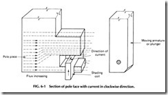
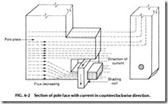
The shaded pole principle is used to provide a time delay in the decay of flux in de coils, but it is used more frequently to prevent a chat ter and wear in the moving parts of ac magnets. A shading coil is a single turn of conducting material mounted in the face of the magnet assembly or armature. The alternating main magnetic flux induces currents in the shading coil, and these currents set up auxiliary magnetic flux which is out of phase from the main flux. The auxiliary flux produces a magnetic pull out of phase from the pull due to the main flux, and this keeps the armature sealed in when the main flux fails to zero (which occurs 120 times/s with 60-cycle ac). Without the shading coil, the armature would tend to open each time the main flux goes through zero. Excessive noise, wear on magnet faces, and heat would result.
Figure 6-1 shows an exaggerated view of a pole face with a copper band or short-circuited coil of low resistance connected around a portion of the pole tip. When the flux is increasing in the pole from left to right, the induced current in the coil is in a clockwise direction.
The magnetomotive force produced by the coil opposes the direction of the flux of the main field. Therefore, the flux density in the shaded por tion of the iron will be considerably less, and the flux density in the un shaded portion of the iron will be more than would be the case without the shading coil.
Figure 6-2 shows the pole with the flux still moving from left to right but decreasing in value. Now the current in the coil is in a counter clockwise direction. The magnetomotive force produced by the coil is in the same direction as the main unshaded portion. Therefore, the flux density in the shaded portion of the iron will be considerably less than it would be without the shading coil. Consequently, if the electric circuit of a coil is opened, the current decreases rapidly to zero, but the flux decreases much more slowly due to the action of the shading coil.
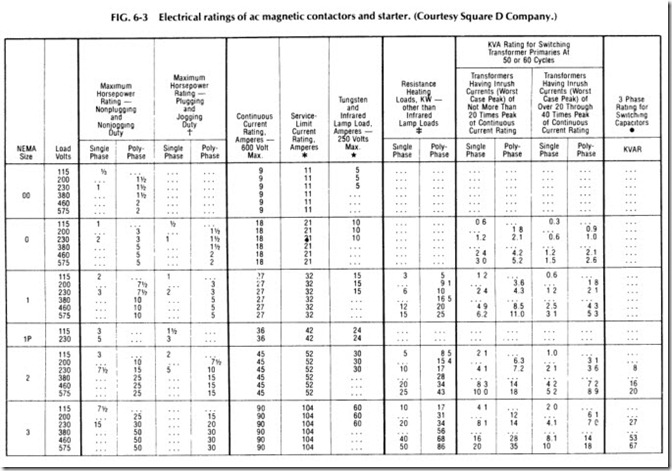
Electrical ratings for ac magnetic contactors and starters are shown in Fig. 6-3.
Tables and footnotes are taken from NEMA Standards
T Ratings shown are for applications requiring repeated 1nterrupt1ons of stalled motor current or repeated closing of high transient currents encountered in rapid motor reversal, involving more than five openings or closings per minute and more than ten in a ten-minute period , such as plug-stop, plug-reverse or Jogging duty. Ratings apply to·single speed and multi-speed controllers.
*Per NEMA Standards paragraph IC 1-21A.20, the service-limit current represents the maximum rms current, in amperes, which the controller may be expected to carry for protracted periods in normal service. At service-limit current ratings, temperature rises may exceed those obtained by testing the controller at its continuous current rating. The ultimate trip current of over-current (overload) relays or other motor protective devices shall not exceed the service-limit current ratings of the controller .
*FLUORESCENT LAMP LOADS- 300 VOLTS AND LESS- The characteristics of fluorescent lamps are such that it is not necessary to derate Class 8502 contactors below their normal continuous current rating. Class 8903 contactors may also be used with fluorescent lamp loads. For controlling tungsten and mfrared lamp loads, and resistance heating loads, Class 8903 ac lighting contactors are recommended. These contactors are specifically designed for such loads and are applied at their full rating as listed in the Class 8903 Sect1on.
:1: Ratings pply to contactors which are employed to switch the load at the utilization voltage of the heat producing element with a duty which requ1res continuous operation of not more than five openings per minute. Class 8903 Types L and S lighting contac tors are rated for resistance heating loads .
• When discharged, a capacitor has essentially zero impedance. For repetit1ve switch ing by contactor, sufficient impedance should be connected in series to hm1t 1nrush current to not more than 6 times the contactor rated cont1nuous current. In many installations, the impedance of -:;onnecting conductors may be sufficient for th1s pur pose. When switching to connect additional banks, the banks already on the line may be charged and can supply additional available short-c1rcuit current which should be considered when selecting impedance to limit the current.
The ratings for capacitor switching above assume the following maximum available fault currents:
NEMA Size 2-3: 5,000 A RMS Sym . NEMA Size 4-5· 10,000 A RMS Sym NEMA Size 6-8: 22,000 A RMS Sym .
If available fault current is greater than these values, connect suffic1ent 1mpedance in
series as noted in the previous paragraph.
The motor ratings In the above table are NEMA standard ratings and apply only when the code letter of the motor Is the same as or occurs earlier in the alphabet than Is shown in the table below.
Motors having code letters occurring later in the alphabet may require a larger controller. Consult local Square D field office.
OVERLOAD PROTECTION
Overload protection for an electric motor is necessary to prevent burnout and to ensure maximum operating life. Electric motors will, if permitted, operate at an output of more than rated capacity. Conditions of motor overload may be caused by an overload on driven machinery, by a low line voltage, or by an open line in a polyphase system, which results in single phase operation. Under any condition of overload, a motor draws exces sive current that causes overheating. Since motor winding insulation deteriorates when subjected to overheating, there are established limits on motor operating temperatures. To protect a motor from overheating, overload relays are employed on a motor control to limit the amount of current drawn. This is overload protection, or running protection.
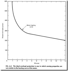
The ideal overload protection for a motor is an element with current sensing properties very similar to the heating curve of the motor (see Fig. 6-4) which would act to open the motor circuit when full-load current is exceeded. The operation of the protective device should be such that the motor is allowed to carry harmless overloads but is quickly removed from the line when an overload has persisted too long.
Fuses are not designed to provide overload protection. Their basic function is to protect against short circuits (overcurrent protection). Motors draw a high inrush current when starting, and conventional single-element fuses have no way of distinguishing between this tempo rary and harmless inrush current and a damaging overload. Such fuses,
chosen on the basis of motor full-load current, would “blow” every time the motor is started. On the other hand, if a fuse were chosen large enough to pass the starting or inrush current, it would not protect the motor against small, harmful overloads which might occur later.
Dual element or time delay fuses can provide motor overload protec tion but suffer the disadvantage of being nonrenewable and must be replaced.
The overload relay is the heart of motor protection. It has inverse trip time characteristics, permitting it to hold in during the accelerating period (when inrush current is drawn) yet providing protection on small overloads above the full-load current when the motor is running. Unlike dual element fuses, overload relays are renewable and can withstand repeated trip and reset cycles without the need of replacement. They can not, however, take the place of overcurrent protective equipment.
The overload relay consists of a current-sensing unit connected in the line to the motor, plus a mechanism, actuated by the sensing unit, which serves to directly or indirectly break the circuit. In a manual starter, an overload trips a mechanical latch, causing the starter contacts to open and disconnect the motor from the line. In magnetic starters, an overload opens a set of contacts within the overload relay itself. These contacts are wired in series with the starter coil in the control circuit of the magnetic starter. Breaking the coil circuit causes the starter contacts to open, disconnecting the motor from the line.
Overload relays can be classified as being either thermal or magnetic. Magnetic overload relays react only to current excesses and are not affected by temperature. As the name implies, thermal overload relays rely on the rising temperatures caused by the overload current to trip the overload mechanism. Thermal overload relays can be further subdivided into two types: melting alloy and bimetallic.
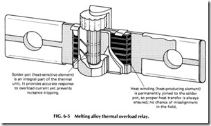
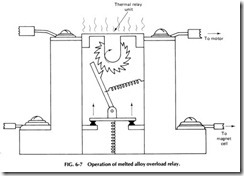
The melting alloy assembly of heater element (overload relay) and solder pot is shown in Fig. 6-5. Excessive overload motor current passes through the heater element, thereby melting an eutectic alloy solder pot. The ratchet wheel will then be allowed to turn in the molten pool, and a tripping action of the starter control circuit results, stopping the motor. A cooling off period is required to allow the solder pot to freeze before the overload relay assembly may be reset and motor service restored.
Melting alloy thermal units are interchangeable and of a one-piece construction, which ensures a constant relationship between the heater element and solder pot and allows factory calibration, making them vir tually tamperproof in the field. These important features are not possible
with any other type of overload relay construction. A wide selection of these interchangeable thermal units is available to give exact overload protection of any full-load current to a motor.
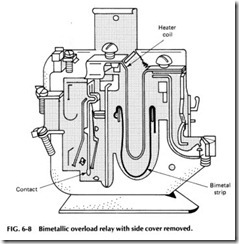
Bimetallic overload relays are designed specifically for two general types of application: The automatic reset feature is of decided advantage when devices are mounted in locations not easily accessible for manual operation, and, second, these relays can easily be adjusted to trip within a range of 85-115o/o of the nominal trip rating of the heater unit. This feature is useful when the recommended heater size might result in unne cessary tripping, while the next larger size would not give adequate pro tection. Ambient temperatures affect overload relays operating on the principle of heat.
Ambient-compensated bimetallic overload relays were designed for one particular situation, that is, when the motor is at a constant tempera ture and the controller is located separately in a varying temperature. In this case, if a standard thermal overload relay were used, it would not trip consistently at the same level of motor current if the controller tempera ture changed. This thermal overload relay is always affected by the sur rounding temperature. To compensate for the temperature variations the controller may see, an ambient-compensated overload relay is applied. Its trip point is not affected by temperature, and it performs consistently at the same value of current.
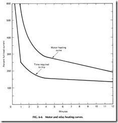
Melting alloy and bimetallic overload relays are designed to approx imate the heat actually generated in the motor. As the motor tempera ture increases, so does the temperature of the thermal unit. The motor and relay heating curves (see graph in Fig. 6-6) show this relationship. From this graph we can see that no matter how high the current drawn, the overload relay will provide protection, yet the relay will not trip out unnecessarily. See Figs. 6-7 and 6-8.
When selecting thermal overload relays, the following must be con sidered:
1. Motor full-load current
2. Type of motor
3. Difference in ambient temperature between motor and con troller
Motors of the same hp and speed do not all have the same full-load cur rent, and the motor nameplate must always be referred to to obtain the full-load amps for a particular motor. Do not use a published table. Ther mal unit selection tables are published on the basis of continuous-duty motors, with a 1.15 service factor, operating under normal conditions. The tables are shown in the catalog of manufacturers and also appear on the inside of the door or cover of the motor controller. These selections
will properly protect the motor and allow the motor to develop its full hp, allowing for the service factor, if the ambient temperature is the same at the motor as at the controller. If the temperatures are not the same or if the motor service factor is less than 1.15, a special procedure is required to select the proper thermal unit.
Standard overload relay contacts are closed under normal conditions and open when the relay trips. An alarm signal is sometimes re quired to indicate when a motor has stopped due to an overload trip. Also, with some machines- particularly those associated with continu ous processing-it may be required to signal an overload condition rather than have the motor and process stop automatically. This is done by fit ting the overload relay with a set of contacts which close when the relay trips, so completing the alarm circuit. These contacts are appropriately called alarm contacts.
A magnetic overload relay has a movable magnetic core inside a coil which carries the motor current. The flux set up inside the coil pulls the core upward. When the core rises far enough, it trips a set of contacts 011 the top of the relay. The movement of the core is slowed by a piston work ing in an oil-filled dash pot mounted below the coil. This produces an inverse-time characteristic. The effective tripping current is adjusted by moving the core on a threaded rod. The tripping time is varied by uncov ering oil bypass holes in the piston. Because of the time and current ad justments, the magnetic overload relay is sometimes used to protect motors having long accelerating times or unusual duty cycles.
PROTECTIVE ENCLOSURES
The correct selection and installation of an enclosure for a particular ap plication can contribute considerably to the length of life and trouble-free operation. To shield electrically live parts from accidental contact, some form of enclosure is always necessary. This function is usually fulfilled by a general-purpose, sheet steel cabinet. Frequently, however, dust, mois ture, or explosive gases make it necessary to employ a special enclosure to protect the motor controller from corrosion or the surrounding equip ment from explosion. In selecting and installing control apparatus, it is always necessary to consider carefully the conditions under which the ap paratus must operate; there are many applications where a general purpose enclosure does not afford protection.
The Underwriters’ Laboratories have defined the requirements for protective enclosures according to the hazardous conditions, and the N a tiona! Electrical Manufacturers Association has standardized enclosures from these requirements:
NEMA 1-General purpose: The general-purpose enclosure is in tended primarily to prevent accidental contacts with the enclosed ap paratus. It is suitable for general-purpose applications indoors where it is not exposed to unusual service conditions. A NEMA 1 enclosure serves as protection against dust and light indirect splashing but is not dust tight.
NEMA 3-Dusttight, raintight: This enclosure is intended to pro vide suitable protection against specified weather hazards. A NEMA 3 enclosure is suitable for application outdoors, on ship docks, on canal locks, on construction work, and in subways and tunnels. It is also sleet resistant.
NEMA 3R-Rainproof, sleet resistant: This enclosure protects against interference in operation of the contained equipment due to rain and resists damage from exposure to sleet. It is designed with conduit hubs and external mounting as well as drainage provisions.
NEMA 4- Watertight: A watertight enclosure is designed to meet a hose test which consists of a stream of water from a hose with a l-in. nozzle, delivering at least 65 gal/min. The water is directed on the enclosure from a distance of not less than 10 ft and for a period of 5 min. During this period, it may be directed in any one or more directions as desired. There shall be no leakage of water into the enclosure under these conditions. Such an enclosure is suitable for applications outdoors on ship docks and in dairies, breweries, and the like.
NEMA 4X- Watertight, corrosion resistant: These enclosures are generally constructed along the lines of NEMA 4 enclosures except they are made of a material that is highly resistant to corrosion. For this rea son, they are ideal in applications such as paper mills and meat packing,
fertilizer, and chemical plants where contaminants would ordinarily destroy a steel enclosure over a period of time.
NEMA 7-Hazardous locations-class I: These enclosures are designed to meet the application requirements of the National Electrical Code for class I hazardous locations. In this type of equipment, the cir cuit interruption occurs in air.
Class I locations are those in which flammable gases or vapors are or may be present in the air in quantities sufficient to produce explosive or ignit ible mixtures.
NEMA 9-Hazardous locations-class II: These enclosures are designed to meet the application requirements of the NE Code for class II hazardous locations.
Class II locations are those which are hazardous because of the presence of combustible dust.
The letter or letters following the type number indicates the particu lar group or groups of hazardous locations (as defined in the NE Code) for which the enclosure is designed. The designation is incomplete without a suffix letter or letters.
NEMA 12-Industrial use: This type of enclosure is designed for use in those industries where it is desired to exclude such materials as dust, lint, fibers and flyings, oil seepage, or coolant seepage. There are no conduit openings or knockouts in the enclosure, and mounting is by means of flanges or mounting feet.
NEMA 13- Oiltight, dusttight: NEMA 13 enclosures are gener ally made of cast iron, gasketed to permit use in the same environments as NEMA 12 devices. The essential difference is that, due to its cast housing a conduit entry is provided as an integral part of the NEMA 13 enclosure, and mounting is by means of blind holes rather than mounting brackets.
NATIONAL ELECTRICAL CODE REQUIREMENTS
The National Electrical Code deals with the installation of equipment and is primarily concerned with safety-the prevention of injury and fire hazard to persons and property arising from the use of electricity. It is adopted on a local basis, sometimes incorporating minor changes or inter pretations, as the need arises. NE Code rules and provisions are enforced by governmental bodies exercising legal jurisdiction over electrical in stallations and used by insurance inspectors. Minimum safety standards are thus assured.
Motor-control equipment is designed to meet the provisions of the NE Code. Code sections applying to the industrial control devices are Article 430 on motors and motor controllers and Article 500 on hazard ous locations.
With minor exceptions, the NE Code, along with some local codes, requires a disconnect means for every motor. A combination starter con sists of an across-the-line starter and a disconnect means wired together in a common enclosure. Combination starters include a blade-disconnect switch, either fusible or nonfusible, while some combination starters in clude a thermal-magnetic trip circuit breaker. The starter may be con trolled remotely with push buttons, selector switches, and the like, or these devices may be installed in the cover. The single device makes a neat as well as compact electrical installation that takes little mounting space.
A combination starter provides safety for the operator, because the cover of the enclosing case is interlocked with the external operating han dle of the disconnecting means. The door cannot be opened with the dis connecting means closed. With the disconnect means open, there can be access to all parts, but much less hazard is involved inasmuch as there are no readily accessible parts connected to the power line. This safety feature cannot be obtained with separately enclosed starters. In addition, the cabinet is provided with a means for padlocking the disconnect in the off position.
CONTROL CIRCUITS
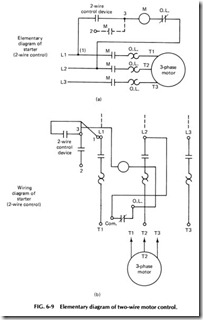
TWO-WIRE CONTROL. Figure 6-9 shows wiring diagrams for a two-wire control circuit. The control itself could be a thermostat, float switch, limit switch, or other maintained contact device to the magnetic starter. When the contacts of the control device close, they complete the coil circuit of the starter, causing it to pick up and connect the motor to the lines. When the control device contacts open, the starter is deener gized, stopping the motor.
Two-wire control provides low-voltage release but not low-voltage protection. When wired as illustrated, the starter will function automat ically in response to the direction of the control device, without the atten tion of an operator. In this type of connection, a holding circuit interlock is not necessary.
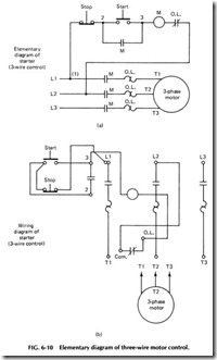
THREE-WIRE CONTROL. A three-wire control circuit uses momentary contact, start-stop buttons, and a holding circuit interlock wired in parallel with the start button to maintain the circuit. Pressing the normally open (N.O.) start button completes the circuit to the coil. The power circuit contacts in lines 1, 2, and 3 close, completing the circuit to the motor, and the holding circuit contact also closes. Once the starter has picked up, the start button can be released, as the now-closed inter lock contact provides an alternate current path around the reopened start contact.
Pressing the normally closed (N.C.) stop button will open the circuit to the coil, causing the starter to drop out. An overload condition, which causes the overload contact to open, a power failure, or a drop in voltage to less than the seal-in value, would also deenergize the starter. When the starter drops out, the interlock contact reopens, and both current paths to the coil, through the start button and the interlock, are now open.
Since three wires from the push-button station are connected into the starter at points 1, 2, and 3, this wiring scheme is commonly referred to as three-wire control. See Fig. 6-10.
The holding circuit interlock is a normally open (N.O.) auxiliary con tact provided on standard magnetic starters and contactors. It closes when the coil is energized to form a holding circuit for the starter after the start button has been released.
In addition to the main or power contacts which carry the motor cur rent and the holding circuit interlock, a starter can be provided with ex ternally attached auxiliary contacts, commonly called electrical inter locks. Interlocks are rated to carry only control circuit currents, not motor currents. Both N.O. and N.C. versions are available. Among a wide variety of applications, interlocks can be used to control other magnetic devices where sequence operation is desired, to electrically prevent another controller from being energized at the same time, and to make and break circuits to indicating or alarm devices such as pilot lights, bells, or other signals.
The circuit in Fig. 6-11 shows a three-pole reversing starter used in controlling a three-phase motor. Three-phase squirrel cage motors can be reversed by reconnecting any two of the three line connections to the motor. By interwiring two contactors, an electromagnetic method of making the reconnection can be obtained.
As shown in the power circuit (Fig. 6-12), the contacts of the forward contactor-when closed-connect lines 1, 2, and 3 to the motor terminals T1, T2, and T3, respectively. As long as the forward contacts are closed, mechanical and electrical interlocks prevent the reverse contactor from being energized.
When the forward contactor is deenergized, the second contactor can be picked up, closing its contacts which reconnect the lines to the motor. Note that by running through the reverse contacts, line 1 is con nected to motor terminal T3, and line 3 is connected to motor terminal T1. The motor will now run in reverse.
Manual reversing starters (employing two manual starters) are also available. As in the magnetic version, the forward and reverse switching mechanisms are mechanically interlocked, but since coils are not used in the manually operated equipment, electrical interlocks are not furnished.
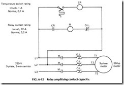
CONTROL RELAYS. A relay is an electromagnetic device whose contacts are used in control circuits of magnetic starters, contactors, solenoids, timers, and other relays. They are generally used to amplify the contact capability or multiply the switching functions of a pilot device.
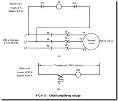
The wiring diagrams in Fig. 6-13 demonstrate how a relay amplifies contact capacity. Figure 6-13(a) represents a current amplification. Relay and starter coil voltages are the same, but the ampere rating of the tem perature switch is too low to handle the current drawn by the starter coil. A relay is interposed between the temperature switch and starter coil.
The current drawn by the relay coil (CR) is within the rating of the tem perature switch, and the relay contact (CR) has a rating adequate for the current drawn by the starter coil.
The other drawing [Fig. 6-13(b)] represents a voltage amplification. A condition may exist in which the voltage rating of the temperature switch is too low to permit its direct use in a starter control circuit operating at some higher voltage. In this application, the coil of the inter posing relay and the pilot device are wired to a low-voltage source of power compatible with the rating of the pilot device. The relay contact, with its higher voltage rating, is then used to control the operation of the starter.
Relays are commonly used in complex controllers to provide the logic or “brains” to set up and initiate the proper sequencing and control of a number of interrelated operations.
In selecting a relay for a particular application, one of the first steps should be a determination of the control voltage at which the relay will operate. Once the voltage is known, the relays which have the necessary contact rating can be further reviewed and a selection made on the basis of the number of contacts and other characteristics needed.
OTHER CONTROLLING EQUIPMENT
TIMERS AND TIMING RELAYS. A pneumatic timer or timing relay is similar to a control relay except that certain of its contacts are de signed to operate at a preset time interval after the coil is energized or de energized. A delay on energization is also referred to as on delay. A time delay on deenergization is also called off delay.
A timed function is useful in applications such as the lubricatfng system of a large machine in which a small oil pump must deliver lubri cant to the bearings of the main motor for a set period of time before the main motor starts.
In pneumatic timers, the timing is accomplished by the transfer of air through a restricted orifice. The amount of restriction is controlled by an adjustable needle valve, permitting changes to be made in the timing period.
DRUM SWITCH. A drum switch is a manually operated three position, three-pole switch which carries an hp rating and is used for manual reversing of single- or three-phase motors. Drum switches are available in several sizes and can be spring-return-to-off (momentary con tact) or maintained contact. Separate overload protection, by manual or magnetic starters, must usually be provided, as drum switches do not in clude this feature.
PUSH-BUTTON STATION. A control station may contain push buttons, selector switches, and pilot lights. Push buttons may be momen tary or maintained contact. Selector switches are usually maintained con tact but they can be spring-return to give momentary contact operation.
Standard-duty stations will handle the coil currents of contactors up to size 4. Heavy-duty stations have higher contact ratings and provide greater flexibility through a wider variety of operators and interchang ability of units.
FOOT SWITCH. A foot switch is a control device operated by a foot pedal used where the process or machine requires that the operator have both hands free. Foot switches usually have momentary contacts but are available with latches which enable them to be used as main tained contact devices.
LIMIT SWITCH. A limit switch is a control device which con verts mechanical motion into an electrical control signal. Its main func tion is to limit movement, usually by opening a control circuit when the limit of travel is reached. Limit switches may be momentary contact (spring return) or maintained contact types. Among other applications,
limit switches can be used to start, stop, reverse, slow down, speed up, or recycle machine operations.
SNAP SWITCH. Snap switches for motor-control purposes are enclosed, precision switches which require low operating forces and have a high repeat accuracy. They are used as interlocks and as the switch mechanism for control devices such as precision limit switches and pres sure switches. They are available also with integral operators for use as compact limit switches, door-operated interlocks, etc. Single-pole, double throw, and two-pole double-throw versions are available.
PRESSURE SWITCH. The control of pumps, air compressors, welding machines, lube systems, and machine tools requires control devices which respond to the pressure of a medium such as water, air, or oil. The control device which does this is a pressure switch. It has a set of contacts which are operated by the movement of a piston, bellows, or dia phragm against a set of springs. The spring pressure determines the pres sures at which the switch closes and opens its contacts.
FLOAT SWITCH. When a pump motor must be started and stopped according to changes in water (or other liquid) level in a tank or sump, a float switch is used. This is a control device whose contacts are controlled by movement of a rod or chain and counterweight, fitted with a float. For closed tank applications, the movement of a float arm is transmitted through a bellows seal to the contact mechanism.
ELECTRONIC CONTROLS
In recent years, many solid-state devices and circuits have entered the motor control field, reducing previously bulky equipment to compact, efficient, and reliable electronic units. Even electric motors have been built on printed circuit boards with all windings made from flimsy copper foil mounted on a flat card.
The Square D NORPAK® Solid State Logic Control is one type of control system that has recently been introduced. The NOR is the basic logic element for NORPAK. Using this single element allows many functions to be obtained through the building block approach. While this results in simplicity of design and the minimum of logic elements in a system, it is also a great benefit when changes are required. While NORs can be connected to form any logic function, it is sometimes more conve nient to have other logic functions available. For this reason, ANDs, sealed ANDs, ORs, and memories are available. Other functions that can not be made up from NORs alone are timers, single shots, transfer memories, counters, and shift registers. This variety of components makes this system a wise choice for any application from simple machine control up to complex systems requiring counting and data manipulation. The basic design of a NORPAK system is the same whether plug-in or encap sulated components are used.
ENERGY MANAGEMENT SYSTEM
The increasing cost of electricity and the shortage of fuel are major items of concern for top management today. Utility bills have risen to levels where action must be taken to help maintain a facility’s profitability.
Most commercial and industrial electric bills are made up of two charges, energy and demand. The energy charge is based on the quantity of energy consumed for the billing period, while in most cases the demand charge is based on the peak electrical energy used during short periods of time called demand intervals.
One possible solution to lowering these demand and energy costs is through the use of an energy management system, which is a technique of automatically controlling the demand and energy consumption of a facility to a lower and more economical level by shedding and cycling noncritical loads for brief periods of time. This can be accomplished by using demand controllers with their basic features or, where economically feasible, by using complex computer-based systems. In some applica tions, these larger systems are justified, but in many cases smaller, less expensive controllers will do the job.
With the advent of the microprocessor, the features of the demand controller along with many of the added features of the computer-based
system have been combined into the Class 8865 EM WATCHDOG Energy Management Systems. The controllers use a continuously integrat ing demand control technique. It is based on an electronic version of the conventional thermal lagged-demand meter. Loads are shed when the predicted demand equals the programmed demand limit.
The priorities, shed and restore times, along with system data can be planned on a data entry worksheet. A calculator-type keyboard is used to enter worksheet data into the controller. A digital readout display con firms that data have been entered.
If a programmed error is made, a digital readout will display an er ror code. To correct an error, the clear entry key is touched, and the cor rect data are reentered. All programming data may then be easily entered or changed.
After all data have been entered, a key switch can be locked into the RUN position which prevents unauthorized persons from changing crit ical load data. While in the RUN mode, the controller’s digital readout will automatically display the predicted demand, the demand limit, and the time of day. All other data settings can be displayed upon request. A battery backup is provided to retain stored information in the event of a power failure.
PROGRAMMABLE CONTROLLERS
Programmable controllers may be used in place of conventional control; they include relays offering faster start-ups, decreased start-up costs, quick program changes, fast troubleshooting, and up-to-date schematic diagram printouts. They also offer additional benefits such as precision digital timing, counting, data manipulation, remote inputs and outputs, redundant control, supervisory control, process control, management report generation, machine cycle, controller self-diagnostics, dynamic graphic displays, and so forth. Applications include machine tool, se quential, process, conveyor, hatching, and energy management control applications. The manufacturer should be contacted for a complete de scription and operation of these systems as even a simple explanation would take more space than can be allotted in this book.
