VIDEO TAPE RECORDING AND REPRODUCTION
The idea of recording and playing back television pictures is as old as television; a primitive video disk was on sale in Selfridges of London in 1938. Yet the first post-World War II experiments in recording television pictures and playing them back were not made with the domestic market in mind. The intention was to remove the stranglehold live television broadcasting imposed on the medium. Repeats were impossible unless the production was shot all over again, or transferred to film.
Recording the signals which went over the air on magnetic tape seemed an obvious solution, but it proved amazingly difficult to achieve. To preserve a picture, vastly more complex information has to be recorded than with the highest quality sound reproduction. Simply recording the finer details of a picture meant a huge increase in the area of tape used to store the information. This meant, in turn, that the speed of the tape over the recording and playback heads had to be much higher than in audio recording.
After years of development, the American company Ampex produced the first working video recorders for broadcast use.
VIDEO TAPE
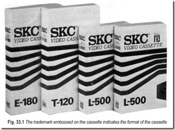
Video tape comes in various widths to fit various tape machines. Every tape machine can work with only one width of tape. There’s 1/4 inch, 8 mm, 1/2 inch, 3/4 inch, 1 inch and 2 inch tape. Format is a term for generic design of a range of hardware. There is more to format than just size; tape speed and other electronic differences which make not all 1/2 inch tapes playable on all 1/2 inch machines. To simplify matters, various manufacturers and video-associations have agreed to standardise on several formats. So if a tape is recorded on a certain format machine, it should playback on the same format machine, regardless of the manufacturer. The most popular formats today are 3/4 U, VHS, Beta and 8 mm. About 90 per cent of homes with video cassette recorders have Video Home System (VHS). Most other have Beta or 8 mm. If you look closely on a video cassette, you may see printed or embossed on the cassette itself the trademark U-matic or the number 8 or the Greek letter β (beta) to indicate the format of the cassette. This is shown in Fig. 33.1.
Video tape for consumer use is available in cassette only and works in basically the same way as an audio tape. Audio tape is used for recording and playback of a rather narrow band of frequencies when compared with video tape. The audio tape recorder handles signals that correspond to the range of human hearing. Video tape is used for recording the picture and any sound that accompanies the picture. Video tape moves more slowly than the one that’s in a typical audio-cassette recorder. In this connection it is imperative that a video tape should contain superior properties in order to provide acceptable performance.
In any cassette, whether audio or video, it is the size of the cassette and the thickness of the tape that determine the amount of tape that can be loaded into the cassette. An increase in running time can be obtained by making the tape thinner and running it at slow speed.
The width of a video tape is generally 1/8 inch to 1/4 inch. The width of video tape for domestic use is 1/2 inch. Although attempts are being made to encourage the use of 1/4 inch tape, the tape most commonly used today by non-professionals has a width of 1/2 inch (12.7 mm)
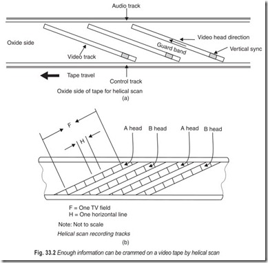
Early professional video recorders recorded video tracks across a 2 inch (5 mm) wide tape. Since then tapes have grown narrower and narrower, down to Compact Video Cassette (CVC) format 1/4 inch (6 mm) tape. This has been made possible by helical scan, the process of recording tracks at an angle across the tape, done by a pair of recording heads on a high speed rotating drum. If the heads were fixed as in audio, the tape would have to move impossibly fast for enough information to be crammed on to it, Fig. 33.2.
PROBLEMS IN VIDEO RECORDING ON TAPE
At first, it might seem very easy to record colour television pictures on magnetic tape. After all, it is only necessary to feed the composite video signal into a tape deck, record it just like audio, and then replay the output of the tape deck into the antenna socket of a television receiver. However, there are many problems. The first problem is that the frequency range needed to record video is much wider than that for audio. A hi- fi audio signal has bandwidth, or frequency range, of around 20 kHz. But a colour television signal, as broadcast or relayed down a cable, has a bandwidth of around 5 MHz. Frequencies of this magnitude are necessary to control the electron beams as they scan several hundred lines of the picture, several dozen times a second.
Remember too, that the scanning electron beam is continually changing in strength, so that the spot of light it makes on the television screen is continually changing in brilliance. The three beams of a colour tube need to be controlled to an accuracy of literally millionths (10–6) of a second, hence the need to handle frequencies of millions of cycles a second. If this kind of high-frequency signal is fed into an ordinary audio tape recorder, the high frequencies which have very short wave lengths—just merge into one another to make an indecipherable mush.
There is also a problem concerning synchronisation. The electron beams have to be kept very accurately in step and for this some very precisely timed synchronisation pulses are necessary. Any slight deviation in the speed of the recorded tape will alter the timing of the pulses and upset the picture synchronisation, making it tear sideways or roll vertically.
EARLY VIDEO
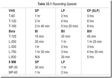
It is possible to improve the frequency response and bandwidth of an audio recorder by increasing the tape speed. So early attempts at video recording adopted the obvious approach. They ran the tape very fast to widen the bandwidth sufficiently to cope with video. Engineers did succeed in recording television signals this way. But when a reel tape runs very fast, it runs out very quickly. So even a large reel only lasts for a few minutes. Also, machines of this type are mechanically very unstable. It is very difficult to get the synchronisation pulses accurately timed. This is why this technique called Longitudinal Video Recording (LVR) fell by the wayside. Recording speeds for different formats are given in Table 33.1.
The concept of LVR was investigated again by BASF in Germany and Toshiba in Japan. Both firms built prototype longitudinal video recorders intended for domestic use. But they were never launched in the market because by then another technique called helical scan had completely taken over. There was just no point in offering an alternative approach that was neither cheaper nor better.
Helical scan was the brainchild of an American company called Ampex. The big breakthrough came in 1956, when the Ampex Corporation demonstrated the world’s first practical video tape recorder at a conference of the National Association of Broadcasters in Chicago. A team of Ampex engineers (including Ray Dolby who was later to become famous for his noise-reduction systems) had finally succeeded in recording television pictures on slow-running tape. They used frequency modulation (FM), as standard for high-quality stereo radio transmissions.
Previous attempts at video recording had relied on amplitude modulation (AM), as used for low-quality medium and long wave-radio. Ampex also abandoned the idea of trying to run the tape very fast through a machine. Instead they used wide tape (50 mm. or 2 inch wide) and ran it slowly (38 cm or 15 ips) past a rapidly rotating drum which carried four video heads. As the drum rotated over the slowly moving tape, the video heads laid as series of recording tracks across the width of the tape, like the rungs of a ladder. Because the Ampex recorder used four video heads on the rotating drum it was called a quadplex or Quad machine.
Early Quad machines were bulky and inexpensive, and could initially only record black-and-white pictures. Before long they were modified to record colour, and the Quad format became standard for broadcasters around the world. Machines of this type are still used in many television studios. Soon afterwards the technique was modified for use with narrower tape. Ampex in the United States and Toshiba in Japan, who were working in parallel, both came up with the idea of helical scan recording. For helical scan the rotating video drum carries two heads and rotates at an angle to the slowly moving tape. In this way the heads lay a series of oblique recording tracks across the tape width, like the helical threads of a screw.
Toshiba built a laboratory prototype helical scan recorder in 1958 and demonstrated it in 1959. In 1960s many different kinds of helical scan recorders were produced for professional, industrial and educational use. A few even found their way into homes for domestic use. But they were difficult to use and offered limited recording time. The tape was one half or one quarter the width of Quad tape, but it was still on open spools that had to be threaded through a tortuous path around the video head drum. The video heads are very fragile, and clumsy threading could easily cause expensive damage. Even the largest reel of tape could offer less than an hour’s playing time. Compared to what video-home offers today, with a playing time in excess of 4 hours, the early helical scan machines were very primitive.
FM MODULATION
The techniques involved to record and replay video signals are not so straight forward as for audio signals. The main problem is the relatively large bandwidth of the video signals which for a broadcast-standard signal extends from dc (about 25 Hz in practice) to 5.5 MHz. For domestic video recorders a more limited response is adequate, the HF roll-off occurs at about 2.5 MHz, permitting more in sparing use of the tape.
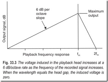
A magnetic tape system’s output level is proportional to therate of change of the magnetic flux, so that output is directly geared to frequency. Thus each halving of frequency (octave) halves the output signal, giving the tape/head interface a characteristic 6 dB/octave curve, Fig. 33.3. Because the difference in levels between magnetic saturation of tape’s coating and the inherent noise of the system is about 1000:1, corresponding to 60 dB, it is plain that the 6 dB/ octave will permit a maximum of tenoctaves to be fitted between the noise floor and the overload point, so long as massive compensation is provided to equalise replay levels across the frequency spectrum.
A television signal, even the bandwidth—restricted one described above, occupies fifteen or sixteen octaves and so cannot be directly recorded on tape by any means. Indirect methods of recording are possible, however, and they involve modulation of the video signal onto a carrier. Invariably an FM carrier is chosen for this purpose. The use of FM increases noise immunity, masks shortfall in signal strength stemming from slight tracking errors and imperfect head/tape contact, and permits either (a) its use as recording bias for a second signal carrying the chroma information or (b) the facility to drive the tape coating into magnetic saturation on each FM carrier cycle to further improve S/N ratio.
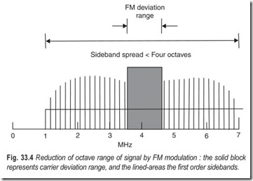
The way in which the FM carrier technique reduces the octave range is shown in Fig. 33.4. Carrier frequencies are assigned for both extremes of the luminance signal waveform, typically 3.8 MHz for sync tip and 4.8 MHz for peak white. This actually permits the recording of dc (zero frequency) video signals since a constant level of white or grey will give a constant FM carrier frequency. During each line sync pulse the carrier falls to 3.8 MHz for its 4.7 µs duration, and during 52 µs active line period the carrier frequency rapidly deviates from 4.1 to 4.8 MHz to describe the levels of light and shade in the TV picture.
In deviating this way, the FM modulator produces sidebands, and the modulation index (the relationship between video and FM frequencies) is chosen so that virtually all the sideband energy is confined to the first pair of sidebands above and below the carrier frequency itself. In the VHS system, for instant, enough sideband energy is recovered to properly demodulate the FM signal when the record and replay frequency response extends from 1 MHz to about 7 MHz, which embraces the entire lower sideband and a portion of the upper one—balance is restored by careful shaping of the frequency response of the playback amplifier. An operating range of frequencies between 1 and 7 MHz represents an octave range of less than four—well within the capability of the magnetic tape system.
HEAD GAP AND WRITING SPEED
Although the octave range has necessarily been reduced using an FM carrier system the maximum frequency required to be recorded has greatly increased. Peak white occurs at 4.8 MHz, and the upper sideband signal— most extensive when sharply-defined detail is being recorded—extends towards 8 MHz. The head/tape transfer system must be capable of passing such frequencies and the magnetic surface of the tape capable of retaining them. The period of an 8 MHz signal is 125 µs and during this short time enough tape must traverse the video head gap to adequately imprint the entire cycle as a magnetic pattern in the tape coating. With a typical head gap of 0.5 microns (5 × 10⁻⁷m) the tape-to-head speed needs to be 5 m/s; this is called writing speed.
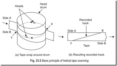
The achievement of such a high writing speed is very difficult in a direct transport system, where extremely high spool and capstan speeds would be required. A solution is to rotate the heads themselves against the tape; the heads are mounted on a spinning head-drum, and protrude beyond its surface to make intimate contact with the tape ribbon which itself is wrapped around the drum. For domestic (and many professional) video formats the arrangement takes the form of helical-scan setup illustrated in basic form in Fig. 33.5.
HELICAL TAPE SCAN
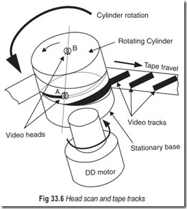
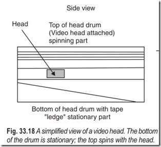
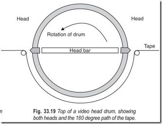
The tape is wrapped around approximately 180° of the drum’s periphery and takes a helical path due to the tilting of the head drum and a precision-machined guide rabbet on the lower (stationary) part of the head- drum. The head assembly spins anticlockwise at 1500 r.p.m. which confers the required high writing speed. All that is required of the tape transport system now is that it moves the tape along by one track-width per head scan in order that successive tracks are laid down side by side and just abutting each other during record. At playback the same tape transport system ensures that as each new head sweep presents itself to the tape wrap a fresh track is lined up in its path for readout. In a typical system using 49 µm wide video tracks the tape progresses through the deck at 2.34 cm/s, pulled around the head drum by a downstream capstan/pinchwheel assembly. At the entry and exit points of the tape head-drum wrap are positioned guides which precisely align the path of the tape around the drum.
The head-tips must maintain intimate contact with the magnetic surface of the tape. In audio-recorder practice this is achieved by pressure-pads which hold the tape tight against the heads. That is obviously impractical in a helical-scan system, where a degree of lateral tension is imparted to the tape in its head-wrap by (a) a back-tension brake on the feed spool and(b) the friction of the tape against the surfaces of the upper and lower head drum’s sections. Against the taut tape ribbon the rotating video head-tips, which project about 50 µm from the drum face surface, push out a moving stretch-spot in which the required head-tape pressure is set up.
Because the tape wrap only covers half the circumference of the head drum, and signal transfer must take place all the time, conventional domestic head drums are fitted with two videoheads. As one leaves the tape wrap at the end of a scan, another (diametrically opposite) begins a new scan of the tape. The signals
from each head are routed in turn into the replay amplifiers by a switch during playback—the switch is synchronised by a head-position sensor associated with the head drum. During record both heads are driven with write signals, though only the one traversing the tape is recording at any one moment.
The transfer of video signals to and from the spinning video heads is accomplished by a rotating transformer whose ferrite core is arranged as two shallow discs concentric with the head drum itself. One half is stationary and the other half rotates with the head disc, magnetic coupling between the two taking place via a very small air gap. One pair of windings is provided for each head; in multi-head machines three or four pairs of windings are required. Separate rotary heads are employed for hi-fi sound signal transfer. For these a separate rotary transformer assembly is usually provided.
DOMESTIC VIDEO
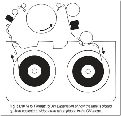
The first big breakthrough that led to today’s boom in domestic video came from Japan and Holland. In 1970 Sony, JVC and Matsushita of Japan agreed to adopt a uniform standard, theU-format, for industrial and semi-professional video. U-format machines went on sale two years later, and have now become the industrial standard, worldwide. They are also used for education and broadcasting. The U-format recorder uses tape which is 19 mm or 3/4 in wide and is contained in a cassette. The user does not need to thread the tape round the videodrum. All this is done automatically as the cassette is loaded in the machine.
At the same time in Europe, Philips of Holland also unveiled a cassette video recorder, the N-1500 series of VCR machines. The first Philips VCRs, shown in 1972, were intended for industrial and educational use. Two years later Philips produced a domestic version. The Philips VCR used 12.5 mm or 1/2 in tape in a cassette, automatically threaded by the machine mechanics. Both the U-matic and Philips VCR could only offer upto one hour’s playing time from a single cassette. This is more than enough for industrial use but indequate for the home where most people want to tape programs off air that last for more than an hour.
The U-format proved to be far more reliable as an industrial machine than the Philips VCR. The U-format was never intended as a domestic format. It required clumsy add-on units to make it suitable for off-air taping and replay through a domestic television set. But the Philips VCR had these features built in. For a few years, in the mid – 1970s, the Philips VCR sold fairly well on the domestic market in Europe even though maximum playing time remained at one hour per cassette, and it cost a relatively large amount of money to feed it with tape.
SLANT AZIMUTH SYSTEM
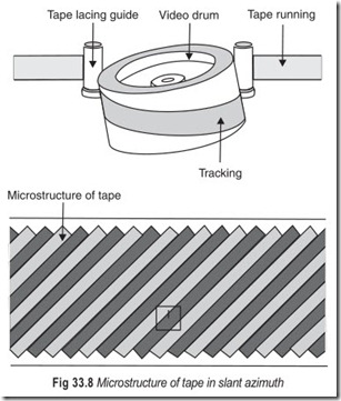
Meanwhile in Japan, all the major electronics companies were striving to produce a domestic video unit that would record for longer than 1 hour, and would be relatively cheap to feed it with tape. In Europe, Philips was also carrying out similar research. Many different formats were developed and several were launched in the market. The next breakthrough which opened the door to longer playing time and cheaper feeding costs, was the rediscovery of an idea patented in 1964 by Prof. Okamura of Japan. This is the so called slant azimuth system, which is used on every modern domestic video recorder, illustrated in Fig. 33.8.
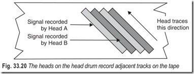
To get more playing time on a given length of tape, all you need to do is run the tape slowly and make the individual tracks narrow, so that the individual helical tracks are packed more closely together. The problem is that if the tracks are too close they interfere with each other and cause crosstalk. The result of Okamura’s idea was to cancel crosstalk on adjacent recordings. It was ideally suited to modern helical scan recorders, which use two heads on the video drum, plus perhaps some extra heads for special effects. If the two heads are set at slightly different angles they will lay down tracks across the tape which have a slightly different characteristic. It is not difficult, then, to ensure that each head can only read its own track and ignore those on either side. To achieve this the azimuth alignment of the recording heads is slightly skewed. The effect is very similar to the loss of high-frequency or treble performance obtained from an audio tape recorder if the playback head is not accurately aligned with the tape. The use of slant azimuth enabled video designers to position the video tracks very tightly together. This is why it is now possible to obtain many hours of recording from the relatively short length of magnetic tape in a modern domestic video cassette.
In Europe Philips modified the original VCR–N-1500 format to use slant azimuth. At the same time the tape speed was slowed. This more than doubled the playing time available from a Philips cassette. The new machines, the VCR–N-1700 series went into the market in late 1977 and early 1978. Soon afterwards Grundig of Germany further modified the tape format, slowing the tape speed even more so that playing time was further extended. But this format, the Grundig Super Video Recorder (SVR) soon became obsolete. So did the Philips N-1700. Both formats were replaced by the Video 2000 format jointly developed by Philips and Grundig.
Philips and Grundig V 2000 machines first appeared on the British market in 1980. However, it was not until 1981 that the format started to produce good results and present any serious competition for the two Japanese formats, VHS and Beta, which had by then gained a very firm foothold in the market place. This is why the V 2000 format, although technically superior, has captured only a small share of the market.
COLOUR RECORDING
The first video tape recorders were for black-and-white signals. Later, methods were developed that permitted the recording of colour signals.
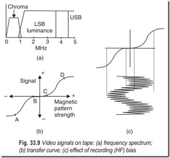
What has been described so far is only concerned with the luminance component of the TV signal. The space between zero and 1 MHz in the tape-frequency spectrum, Fig. 33.4, is reserved for the chroma signals, and to prevent it from being encroached upon by the lower sideband of the luminance FM signal, the rise time and frequency range of the latter are reduced in the pre-modulator luminance processing stages; any short comings in this bandpass filter will permit luma and chroma signals to cross-modulate with consequent patterning in the playback picture.
The colour signal is recorded direct onto the tape without any form of modulation system. It is already encoded and based on a 4.43 MHz subcarrier whose phase and amplitude relative to the accompanying burst signal describe the colours in the picture. To interfere in any way with the chroma signal would be to invite hue and saturation errors ; to decode and demodulate it to baseband for recording and encode/modulate it during replay would be a complex and unpredictable business. The PAL colour signal cannot be recorded in its 4.43 MHz form as broadcast, however, it is above the frequency range of the baseband signals that the system can handle; the timing jitter introduced by the mechanics of the recording/playback process would play havoc with the phasing of the subcarrier signal and hence hue; and the bandwidth demand would be too great to accommodate in the limited tape spectrum. Two processes are carried out on the chroma signal to slot into the 0–1 MHz space assigned to it. It is bandwidth restricted in a bandpass filter which limits its sideband excursions to + 500 kHz on each side of the carrier frequency; and it is frequency shifted by a heterodyne process to a new base frequency around 600 kHz. Thus is formed a lower-definition, lower- frequency chrominance signal with all characteristics of phase, amplitude and burst features intact. The new frequency allocation and clipping of wings tailors it for the position it occupies in the tape-frequency spectrum. It is added to the FM luminance signal and passed to the heads for recording. Fig. 33.9 (a) shows the complete signal spectrum on tape.
Because the transfer characteristic of magnetic tape is not linear, Fig. 33.9 (b), a recording bias must be provided and added to the signal to be recorded if severe distortion is not to take place. It is normal practice in audio tape recorders to add a relatively high-frequency (say 40 kHz) switching signal to the audio waveform before it is applied to the recording head; the locally generated bias signal is very carefully controlled in amplitude so that its peaks sit in the centres of the linear section A–B and C–D in Fig. 33.9 (b). As the record signal is rapidly switched between the two centre points by the bias signal, it is printed in linear fashion as magnetic patterns in the tape, as Fig. 33.9 (c) shows. The ability to work on both sections of the transfer curve increases the replay level and improves S/N .
In the colour-under recording system used in domestic video recorders the FM luminance carrier acts as ac bias source for the low-frequency chrominance signal. The two are added in the recording amplifier, and the variations in bias frequency do not matter at all—during replay a low-pass filter in the chrominance amplifier removes all signal components above 1 MHz.
For the scheme to work the levels of both FM luminance carrier and chrominance signal must be closely controlled and their pre-set amplitudes depend very much on the characteristics of the tape to be used. The level of the FM carrier—luminance writing current—must be set to take the tape’s magnetic coating half way to saturation in each direction. The chrominance record level then must be trimmed so that the largest expected colour signal amplitude (fully saturated cyan or red) drives the magnetic surface of the tape to just short of saturation in the positive direction, and to just short of non-linearity in the negative direction. Correct setting of these levels ensures low signal distortion and maximum S/N ratio.
In the audio world, different tape materials (oxide, metal, chrome, etc.) are available, and need different bias and drive settings for optimum performance. For video recorders as yet, the levels are preset to the type of tape available for that format. The metal and metal-evaporated tapes used with Video 8 format have very different bias, coercivity and saturation characteristics to conventional tape as used in other formats. When colour is not present in the signal to be recorded (mainly vintage films) a useful gain in noise performance can be achieved by increasing the gain of the luminance recording amplifier; a 6 dB boost in writing current drives the tape into magnetic saturation in both directions on each cycle of the FM carrier.
VHS AND BETA FORMATS
The Japanese formats, VHS and Beta, each underwent a train of developments in Japan and the United States. For each format, playing time was increased in stages by the introduction of slower tape speeds. In May 1975 Sony announced a Beta video recorder that offered 1 hour’s playing time. In early 1977 the format was modified to give 2 hour’s playing time. At around the same time JVC developed the VHS system, which from the start offered 2 hour’s playing time from a single cassette. Subsequently, options were built in both VHS and Beta machines to increase the playing time further, by switching the machine to run at slower speeds. Thus the actual playing time per cassette depends both on the running speed selected and the length of the tape in the cassette, but around eight hours is now possible.
Beta machines on the American market can be switched between Beta II speed which is 2 cm (0.787 in) per second and Beta III which is 1.3 cm (0.525 in) per second. VHS machines on the American market can be switched between SP mode which is 3.3 cm (1.3 in) per seconds, LP mode which is 1.67 cm (0.65 in) per second and EP mode which is 1.1 cm (0.43 in) per second. In Britain a VHS recorder runs the tape at 2.34 cm (0.9 in) per second, and a Beta machine runs the tape at 1.87 cm (0.73 in) per second. With a normal cassette this gives 3 hours for VHS or 3 hours and 15 minutes for Beta. But 4 hour cassettes, with more tape, are available.
VHS now has stereo capability, though it is nowhere near high fidelity. However, with introduction of FM sound the sound quality on VHS has improved dramatically. Engineers have found a way to encode the audio signal inside the video signal, resulting in a very high quality audio reproduction. As far as picture is concerned it is now possible to obtain professional, high definition pictures from the VHS format, though the equipment is not compatible with domestic VHS, as the machines run at much higher speeds.
One or two manufacturers have now adopted LP or half speed record and play modes. The capacity of a tape is effectively doubled, though there is a noticeable degradation of the picture and sound quality—in practice the reduction in quality shouldn’t matter too much, being quite acceptable.
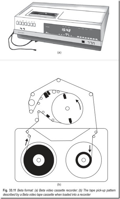
There is, of course, no possibility of playing a Beta cassette on a VHS machine or vice versa. The cassettes are of different size, and the only feature they have in common is the use of tape which is 12.5 mm (1/2in) wide. The picture quality on screen, the sound quality and all the features and facilities which VHS and Beta formats offer are virtually identical.
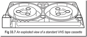
Although VHS and Beta tapes recorded in one country cannot be replayed in another, the cassettes themselves are physically identical. In many respects they are both miniature versions of the industrial U-matic. The two tape spools in the cassette are coplanar, that is the spools are side by side and the tape runs
direct from one spool to the other. One reason for the eventual failure of the philips VCR formats was that the cassette used coaxial spools—in other words, spools stacked one on top of the other. This means that the tape had to run a skew path which made it much more difficult to control. The tape would jam, and even break, especially in ageing cassettes. With modern video recorders it is virtually unheard of for the tape to jam or break in a machine that is working properly.
VIDEO 2000 FORMAT
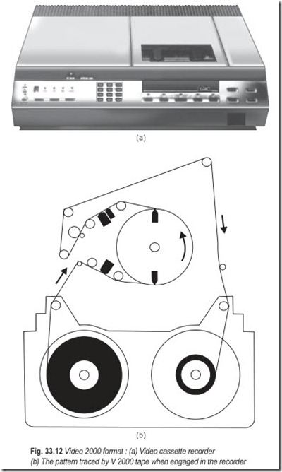
The Philips V 2000 cassette also uses 12.5 mm (1/2in) tape and coplanar spools. It looks very similar to VHS cassette. The tape runs at a speed of 2.44 cm (0.95 in) per second. The major difference between V2000 and the VHS and Beta formats is that only half of a V 2000 tape width is used on each pass through the recorder; the cassette is then taken out, flipped over and put back in the recorder; the tape then passes through the machine in the opposite direction with the other half of its width used. This exactly parallels the situation for audio cassettes where only half the tape width is used on each pass. This approach doubles the playing time but it also means that twice as much video information has to be put onto that tape, because only half its width is being used. It is as if the V 2000 recorder is using 6.25mm (1/4 in) tape.
The information is packed on by making helical tape tracks very narrow and very close together. To ensure that the rotating video heads of a V 2000 machine are kept in accurate alignment with the video tracks across the tape the individual heads are mounted on tiny piezoelectric crystals. All the time that the heads of a V 2000 video recorder are scanning across the tape, they are continually being fed by a control signal that keeps them accurately in line with the tape tracks. This is one reason why the V 2000 format has great potential, technically. It was its late appearance on the market and the poor performance of early V 2000 recorders that handicapped the recorder commercially. All around the world VHS is a clear market leader with Beta second and V 2000 usually well behind.
COMMON FEATURES
Let us forget for the moment the differences between the three formats: VHS, Beta and V 2000. Suffice is to say that each format can now offer virtually identical picture quality, sound quality and all-round performance. The only major remaining difference is the potential of V 2000 to offer auto-reverse. Instead of the user
taking out the cassette and flipping it over, the machine automatically reverses the direction of travel of the tape and switches the video recording heads to work on the other half of the tape width. This can be done with the picture lost for only a couple of seconds. Again this parallels the auto-reverse facility offered by some audio cassette recorders and it effectively doubles the continuous playing time available from a similar cassette. Obviously auto-reverse cannot be offered by VHS and Beta because each of these formats utilises the full tape width on the first pass.
All the formats offer exactly the same basic facilities. They all record and replay colour television pictures and sound. Originally they could record only mono sound, but modern machines record in stereo. Every domestic video recorder since the original Philips VCR–N-1500 has had three features which were available only as expensive optional extras for the U-Format machines. Every domestic recorder has a built- in tuner, a built-in modulator and a built-in timer.
8 MM FORMAT
The 8 mm video format has been designed to meet the requirements of smaller size and lighter weight. The 8 mm video tape is only 8 mm wide as compared to the VHS video tape, which is only 12.6 mm wide. As a result the mechanism is much smaller. In the 8 mm video system, the tape runs at 14.3 mm per second and utilises a 40 mm drum with a 221° wrap.
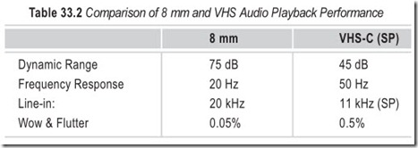
The 8 mm format features an FM hi-fi audio recording system. The audio signal is recorded as an FM carrier. Although most 8 mm systems can only record mono audio, provisions have been made in the format to record stereo pulse code modulation (PCM) audio. As Table 33.2 shows, this gives 8 mm a far better performance than VHS-C (C for compact) with a 75 dB dynamic range and a low 0.05 per cent wow and flutter rating.
Using an advanced metal tape formulation, the 8 mm metal particles boast four times the magnetic energy of the conventional cobalt ferric-oxide tape used in VHS-C. This tape enables 8 mm to record and playback video signals with much less dropout.
The 8 mm video track does not use a conventional control track head, but the Automatic Track Finder (ATF) circuit. With this circuit, the VCR monitors the video head position and compensates for error in the tape path. This new format and design results in a compact and low weight high quality camera recorder (camcorder).
VIDEO TAPE FORMAT PARAMETERS
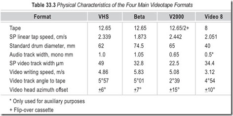
Table 33.3 gives a comparison of the main physical features of each format in current use. In comparing the data, the following general points should be borne in mind.
(a) Narrow video tracks give high recording density on tape but an inferior noise performance; at track widths below 25 microns good tracking is difficult to achieve with a Dynamic Track Following (DTF) or Automatic Track Finder (ATF) system.
(b) Head drum diameter is directly related to video-track writing speed; the larger the drum (for a given wrap angle, i.e. 180 degree) the greater the writing speed and the wider the frequency response.
(c) Linear tape speed determines the sound-channel frequency response where longitudinal tracks are used—the higher the speed the greater the frequency range.
(d) Longitudinal track audio S/N ratio depends on track-width; the half-width stereo tracks for use with stationary audio heads have the worst S/N ratio.
(e) All half-wrap head drums for use with 50 fields and TV systems rotate at 1500 rpm in order that one-half revolution occupies exactly the period of one TV field; in 60 Hz systems the head-drum speed is 1800 r.p.m.
VIDEO TAPE TRACK CONFIGURATION
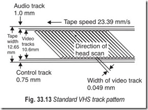
The standard VHS track pattern is shown in Fig. 33.13. The tape advances at 2.34 cm/s to give tracks 49 microns wide. They are scanned from bottom to top of the tape. The upper edge is reserved for a conventional sound track 1 mm wide, which for stereo is split into two 0.35 mm tracks separated by a 0.3 mm guard band. The lower tape edge carries the control track, which provides a poisoning reference for the video tracks themselves, and is used to guide the head sweeps during replay.
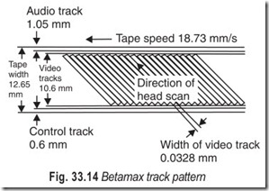
Fig. 33.14 illustrates the Betamax track pattern. Tape width is 12.65 mm again, but video tracks are narrower at 33 microns with a corresponding lower linear tape speed of 1.87 cm/s. The larger Beta head drum of 74.5 cm diameter is responsible for this format’s high writing speed of 5.83 m/s compared with VHS format’s 62 mm drum and 4.86 m/s writing speed.
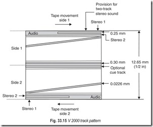
The third format using 12.65 mm tape is the V 2000 system shown in Fig. 33.15. This is a double-sided arrangement with only one-half of the tape width used; in effect it is a 6.3 mm (1/4 in) system sharing with the compact audio cassette the turnover feature whereby both sides can be used to effectively double playing time. V 2000 video tracks are the narrowest of all SP domestic format ones at 23.5 microns calling for a linear tape speed of 2.442 cm/s with the specified head-drum diameter of 65 mm. In laying down these narrow tracks, and particularly in tracing them during replay, head pisitioning is governed by an electronic steering system, a variant of which is also used in the most recently developed format, Video 8.
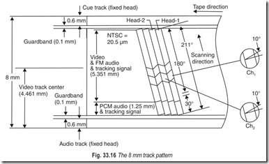
Tape parameters of Video 8 are given in Fig. 33.16. A major departure from previous practice is the tape width. This narrow tape lends iself well to portable, mobile and light weight video applications, especially
since its cassette package (95 × 62.5 × 15 mm) is a little bigger than an audio tape. Except for special applications like program indexing/cueing and other auxilary signals, the V8 format has no need of longitudinally recorded tracks. Tracking control signals in an ATF system are recorded alongwith the video signals themselves, and sound is also carried in the narrow helical tracks—this technique of sound with vision (hi-fi) record and playback is essential in the V8 system since the linear tape speed—approximately 2 cm/s in standard-play mode and 1 cm/s long-play mode—would render very low quality sound from a stationary-head system.
Other features of V8 technology are a facility for Pulse Code Modulation (PCM) audio recording on a 30 degree extension of the video track; a relatively low writing speed of 3.1 m/s, due to the conveniently small head drum diameter of 40 mm; and a 34.5 micron track width, which in LP mode reduces to 17.2 micron.
VIDEO AND AUDIO HEADS
VCRs record and playback audio and video signals using magnetic heads. At a maximum, all VCRs use the following magnetic heads:
(a) A stationary full-erase head
(b) A stationary audio head
(c) Rotating video heads
(d) A stationary control-track head
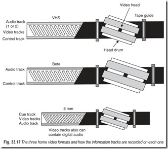
The way these heads record information on the tape is similar for the three formats, though the exact track widths and specifications vary. The recording formats for VHS, Beta, and 8 mm are shown in Fig. 33.17. The relative location of the heads in the three types of VCRs is shown in Fig. 33.18.
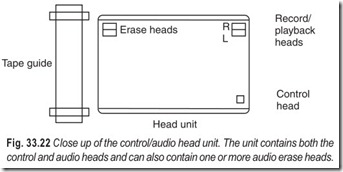
(a) Full-erase head: The full-erase head erases the entire tape and is on only during recording. The erase head blanks out any previous recording that might be on the tape. In some VCRs a secondary audio erase head can be used. This head erases just the audio track.
(b) Audio head: In the record mode the tape moves past the audio head, where the head impresses the sound signal on a thin track on the edge of the tape. In the playback mode the head picks up the signal recorded on tape.
(c) Video heads : VCRs use rotating heads to record and playback video, Fig. 33.19. The heads are mounted in a polished metal cylinder called the head drum (other names are used as well, including scanner head cylinder and head wheel).
The heads are at an angle so they record a series of long, diagonal tracks on the tape, as shown in Fig. 33.20. The tape might creep slowly through the VCR, but the rotating video headsspin at 1500 revolutions per minute, effectively covering about 250 inches of tape per second.
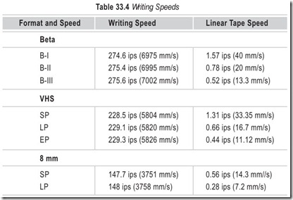
Table 33.4 shows the relative speeds of the tape traveling through a VCR versus writing speed, which is the amount of tape covered by the video heads in one second.
Note: Writing speed increases slightly at slower linear tape traveling speeds.
(d) Control-track head: During recording, the control track records a series of 25 Hz pulses. These pulses are used to synchronise the video heads during playback so they pass directly over the tracks that were previously recorded. Without the control track the video heads might not scan directly over the video tracks, and the picture would be garbled. The control tracks serve the same general purpose as sprocket holes in a movie film. The sprocket holes help align each frame so you see a steady picture on the screen. In almost all VCRs, the control-track head is mounted in the same unit as the audio head.
ADDITIONAL HEADS
Some VCR models incorporate additional heads. These are:
(a) Stereo audio heads
(b) Rotating audio heads
(c) Flying erase head
(a) Stereo audio heads : Monophonic VCRs use a single audio head to record and playback sound. Older stereo VHS decks use a dual audio head for recording the right and left tracks separately. Stationary stereo audio heads are seldom found on home VCRs these days. Audio recording with two audio heads is called linear stereo. The tracks are placed alongside one another near the edge of the tape (see Fig. 33.21) and occupy the same space as the standard mono audio track (monophonic decks pick-up both the right and left channels together). Noise reduction circuitry (such as Dolby) is often used with linear stereo decks to improve the sound quality.
On a number of linear stereo VCRs, one or both of the channels can be independently erased or activated for audio dubbing. The audio erase head is built into the audio head as shown in Fig. 33.22. With audio dubbing, you record only the audio segment, but leave the video and control tracks intact. Most linear stereo decks let you record on either the left or right stereo channel, leaving the other channel untouched. Beta VCRs record stereo audio mixed with the picture information.
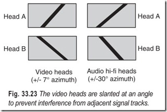
(b) Rotating audio heads : VHS hi-fi decks—those that record stereo sound in high fidelity—have two additional heads mounted with the rotating video heads. These heads record audio information in an FM carrier signal. Even though the audio and video tracks are intermixed, they do not interfere with one another because the azimuths of the heads are different, as depicted in Fig. 33.23. Magnetic heads do not pick-up information that is recorded on substantially different angles. The video heads themselves record at different azimuth angles.
Beta stereo hi-fi decks record picture and high fidelity sound using the machine’s standard complement of video heads. Both the sound and picture are combined in one signal and placed on the tape together.
(c) Flying erase head : The main full erase head erases the contents of the entire tape prior to recording. The 8 mm table top VCRs, top-end VHS and Beta decks, and many 8 mm and VHS camcorders use one (and sometimes two) flying erase heads mounted with the video heads.
The flying erase head (s) erases just the video tracks, leaving the control and audio-tracks alone. A flying erase head provides better, cleaner edits.
Fig. 33.23 The video heads are slanted at an angle to prevent interference from adjacent signal tracks.
VIDEO HEAD GEOMETRIES
The size of the gap found in all magnetic recording heads varies from 28 to 90 microns wide, depending on the application. The video heads in typical VHS decks have a head gap of only 38 microns. The gap in conventional Beta video heads is even smaller, 30 microns, and in 8 mm decks, the gap is 20.5 microns.
VCRs use head gaps of various sizes to improve performance at slower record and playback speeds and to accomplish noise-free special effects. Wider heads record a stronger signal and are desired over narrow head gaps. A problem occurs when using wide heads to record and playback video at the slower LP, EP or BIII speeds.
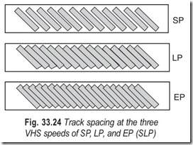
Fig. 33.24 shows the geometry of the video tracks laid down by the video heads with a conventional VHS-VCR at SP, LP and EP speeds VHS design parameters allow for 58 microns between each video track at SP speed. The spacing decreases proportionately at the slower speeds—29 microns and 19 microns for LP and EP speeds, respectively. At the fast speed there are guard bands as wide as 28 microns between the tracks. As the tape slows down, the tracks get closer together and they overlap by as much as 11 microns.
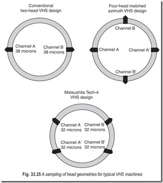
Obviously, if the deck is equipped with wide heads, playback and recording will be satisfactory at the SP speeds because of the guard bands between the tracks. But operation will be severely limited at slower speed because the tracks will almost stack on top of one another during recording.To provide optimum performance at both fast and slow speeds, many VCRs use four heads instead of just two. The gap is wider on one side of the heads. The wide set is designed for SP speeds and the narrow set is for LP and EP speed. The actual size of the head gap varies depending on the make and model. Fig. 33.25 shows the head geometries for popular two and four-head VHS designs from JVC and Matsushita. Note that the head gap is not always the same for opposite heads in the same set. This provides the deck with better performance during playback and with certain special video effects such as still-frame and slow motion.
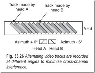
Even at the slow LP and EP speeds with a narrow head the video tracks still overlap. The effects of this inevitable overlap are precluded by tilting the video heads at opposing angles. In VHS system one video head is tilted at + 6° to the centre, and the other is tilted at –6° to the centre as shown in Fig. 33.26. The 12 degree difference in azimuth reduces or eliminates the crosstalk that would otherwise occur if the heads were on the same plane. In Beta decks, the azimuth is +7° and –7°, and in 8 mm the heads are angled + 10°.
HEAD SWITCHING
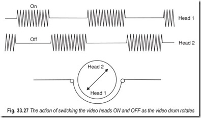
During recording, the signal feeds alternately to the heads via a head switching circuit. The head is turned ON as it touches the tape and makes its half-circle pass around the head drum. Just before the head is about to leave the tape, it turns OFF and the signal is applied to the opposite head. The video waveform for head switching is shown in Fig. 33.27.
VHS HIGH FIDELITY AUDIO
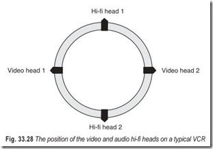
Beta was the first to market a hi-fi VCR. JVC had considerable trouble developing a competing hi-fi audio standard for their VHS decks. The standard VHS recording format does not allow enough space between the luminance sideband and the chrominance carriers even if the luminance carrier could be moved up a few notches. In fact, VHS decks cannot tolerate a change in frequencies. The limitation means that VHS-VCRs cannot use the video heads to record hi-fi audio, as Beta VCRs do. A second set of heads, as shown in Fig. 33.28, are added to the video-head drum. The heads operate in the same manner as video heads. One head in the set records a field’s audio information, the next head records another, and so forth. The gap of the hi-fi heads can vary from about 6 microns to 42 microns.
In the VHS hi-fi system, the audio signals are recorded first, then the video signals are recorded. Normally overrecording with the video heads would lead to complete or partial erasure of the audio track but in practice this does not happen—thanks to an old recording technique.
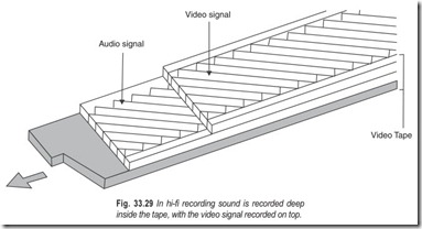
It has been known for many years that low-frequency signals penetrate into the tape further than high- frequency ones. Because the hi-fi audio portion is lower in frequency than the 3.4 to 4.4 MHz luminance carrier, it travels deeper into the tape. JVC calls this technique depth multiplex recording.
During recording the hi-fi heads record their signal a split second before the video heads record theirs. The audio signal goes deeper into the tape, so when the video heads pass by, most of the already-recorded video information remains. To avoid crosstalk between the audio and video carriers, the hi-fi audio heads are tilted at + 30°. The extreme azimuth also reduces crosstalk between right and left stereo channels.
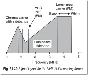
The hi-fi heads record the audio on FM carriers, as shown graphically in Fig. 33.30. The frequencies are 1.3 MHz for the left audio channel and 1.7 MHz for the right audio channel. Compatibility with decks that do not feature hi-fi is retained because the sound also is recorded on the linear audio tracks.
Because the hi-fi audio is recorded with the video track effects such as audio dubbing are not possible. There is no way to selectively erase the audio portion of the program and replace it with another track. However, many VHS hi-fi machines also record stereo audio onto one or two linear audio tracks. These tracks can be selectively erased and recorded.
AUTOTRACKING
One of the banes of using a VCR is fine-tuning the picture using the tracking control. This control compensates for the inevitable difference between VCRs, even when using the same VCR to playback an older tape. Without this control, snow would often appear on the top or bottom of the screen.
8 mm decks and camcorders incorporate an ingenious automatic tracking system, so there’s no need to adjust the tracking control. Tracking controls are common on Beta and VHS decks although a number of the later model VHS units incorporate an autotracking feature. In the VHS autotracking system, electronics in the deck sense when the video signal drops 15 per cent or more during playback. This drop indicates the tracking is off, thereby causing snow at the top or bottom of the picture.
PCM AUDIO
All 8 mm decks can record high fidelity digital sound. The specifications are almost as impressive as those found on audio compact discs : 50 Hz to 15 kHz frequency response; 90 dB signal to noise ratio, 88 dB dynamic range. The analog-to-digital conversion uses 8-bit quantization (by comparison, compact audio discs use superior 16 bit quantization).
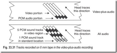
The process of digital recording is known as pulse-code modulation (PCM). In operation, a series of pulses that represents digital data is recorded on the tape. The pulses are derived by converting the original analog audio signal to digital form. For playback the pulses are processed in just the reverse to reconstitute analog audio from the digital. There are two digital audio modes: video-plus-audio and all-audio (the latter is sometimes called multi-PCM). In the video-plus-audio mode, the digital sound is recorded with the video picture (the track also can be added after the picture is recorded). In all-audio mode the deck records only sound. Depending on the recording speed, you can store up to 24 hours of digital sound on a 2 hour tape (12 hours at SP speed). Fig. 33.31 shows the track layout for video-plus-audio and all-audio recording.
In video-plus-audio mode, the PCM audio is placed at the head of each video track. This is accomplished by wrapping the tape further around the head drum, as depicted in Fig. 33.32. The standard 180° wrap is used for video recording, and the extra 30° wrap is used for PCM audio recording. PCM audio is also found on some high-end VHS decks. Most use higher quality 14-bit quantization.
CVBS SIGNAL
TV video signal cannot be recorded directly on tape in its basic form, due to bandwidth and noise problems. This is true of both luminance and chrominance components and each has to undergo a great deal of processing in both record and replay modes, first to convert them to a form amenable to the tape system and then to restore from the off-tape video signals, a video signal which corresponds as closely as possible to that recorded. We have three signals to cater for: luminance, chrominance and sound, and each is handled separately in the VCR. These signals usually come from a common source—the VCR’s detector working on broadcast signals or a TV camera—and are eventually combined (in the VCR’s RF modulator) into a single composite signal with all the characteristics of a broadcast transmission.
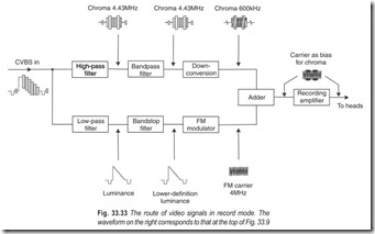
The standard form of the signal which will be found at the video input and output sockets of cameras, VCRs monitors and so on is known as the Chroma, Video, Blanking and Syncs (CVBS) signal. Its level is invariably 1V peak-to-peak. The term luminance is used to describe the V, B and S components which together form the signal information required to respectively describe, stabilise and synchronise a monochrome TV picture. The chrominance part, is in encoded form and based on a frequency of 4.43 MHz. This is above the range of the luminance signal. Simple filters with a bandstop in the region of 3.5 MHz intercept and divert these two vision components into their appointed recording circuits as further elaborated in Fig. 33.33.
BLOCK DIAGRAM OF A VIDEO CASSETTE, RECORDER
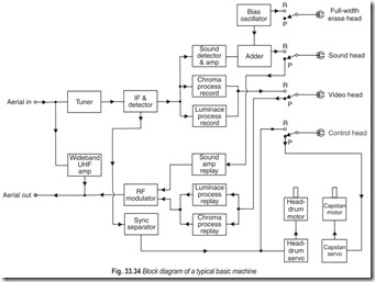
Apart from the deck mechanism the recorder consists of an ensemble of printed circuit panels, each dealing with one or more aspects of the machine’s operation. A block diagram of a typical basic machine, showing signal paths is given in Fig. 33.34.
During record the VCR’s receiver section (tuner, IF and detector) converts broadcast transmissions into baseband sound and vision signals. The sound signal passes to the audio recording head after the addition of a bias signal, which is also fed at high power to the full-width erase head to wipe existing tracks off the tape. The vision signal is split by filters into luminance (black-and-white) and chrominance (colour) components which are dealt separately before being added together for application to the rotating video heads. A sync separator strips the timing pulses (part of the video waveform) from the video signal for processing in the video-head-drum motor servo—they are used to keep the head sweeps synchronised to the picture signal. These timing pulses are also recorded on the tape by the control track head for use as reference during replay.
During playback mode, the tiny signals from the tape heads are switched to replay processing circuits for sound, luminance and chrominance, all three again being separately dealt with. The re-created sound and vision signals come together in the RF modulator, where they are impressed on a UHF carrier, then passed out of the machine en route for the TV set. The control track is replayed into the head drum or capstan servo via a tracking control to enable the video heads to accurately scan the existing tape tracks.
CONTROLS ON VIDEO CASSETTE RECORDERS
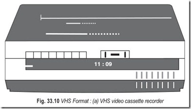
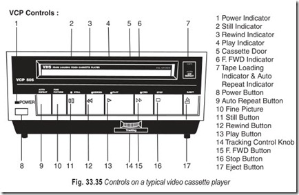
VCPs (video cassette players) lack a recording capability—they only playback tapes and lack the means to record. This means VCPs dispense with a lot of extraneous electronics, as well as the programmable record timer. As a result VCPs are a little less expensive than full-fledged recording VCRs. However they require the same level of mechanical maintenance as full-fledged recording VCRs. The controls on a typical VCP are depicted in Fig. 33.35.
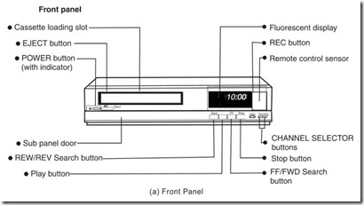
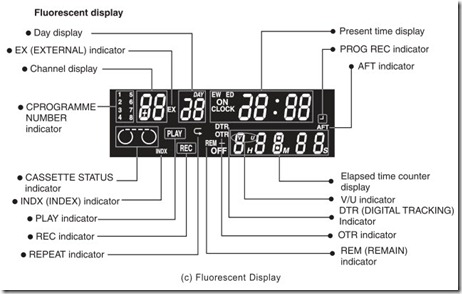
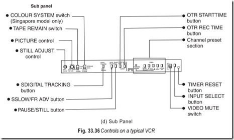
Most VCRs have the following typical controls:
POWER : Turns the power ON and OFF
EJECT : Ejects the cassette from the VCR.
PLAY : Places the deck in the PLAY mode.
FAST FORWARD : Fast forwards the tape; no picture on screen.
REWIND : Rewinds the tape; no picture on screen
CUE (or fast forward scan) : Scans the tape at 3 to 30 times the normal speed in forward; high-speed picture on screen.
REVIEW (or reverse fast scan) : Scans the tape at 3 to 30 times the normal speed in reverse; high-speed picture on screen.
PAUSE : Stops the tape during playback; a still frame appears on the screen (the deck stops automatically after about five minutes to prevent excessive tape and video-head wear).
RECORD : When used with the PLAY button, places deck into RECORD mode.
AUDIO DUB : Records just audio over previously recorded program (video portion must be previously recorded)
VIDEO DUB : Records just video over previously recorded program.
TRACKING : Adjusts tracking to reduce or eliminate noise bars in picture (not found on 8 mm decks).
OTR : One-touch recording; starts deck in RECORD mode and records for preset period. On many decks, each press of the OTR (or EXPRESS) button increases the recording time by 30 minutes.
TIME buttons : Set the record timer.
CLOCK buttons : Set the clock (many decks set the time and day of week).
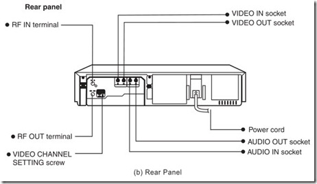
CHANNEL 3/4 output (back of deck) : Switches RF modulator output to channel 3 or 4.
LINE : (With A/V terminals) : Switches between RF or direct AUDIO/VIDEO input terminals (might be automatic on some models).
Most VCRs have a counter and counter RESET. The counter is operated by the take–up spindle (either mechanically or electronically) or the control-track pulses and indicates relative tape position. The counter is reset to “0000” by pressing the RESET button.
EXERCISES
Descriptive Questions
1. What are the problems in video recording and how are these overcome?
2. Describe the basic principle of video recording.
3. Compare audio cassette recording with video cassette recording.
4. What is a format? Compare the three most popular video formats. Enumerate the relative similarities of the three formats.
5. Explain why signals are attenuated as the gap size increases beyond l/2.
6. What is the relation between gap width and writing speed?
7. What techniques are adopted to record and replay video signals?
8. With the help of a suitable sketch, explain the slant azimuth system of video recording.
9. How the colour signal is recorded on the tape?
10. What is the significance of recording bias?
11. Briefly explain the colour-under recording system.
12. Compare video and audio heads.
13. What is the function of a flying-erase head?
14. Explain why head switching is required? How is it done?
15. With the help of a block diagram, explain the working of a basic video cassette recorder on record and replay.
16. Differentiate between a VCP and a VCR. Briefly explain the most-often-used controls on a VCR.
Multiple Choice Questions
1. The most popular formats today are
(a) 3/4 U (b) VHS
(c) V 2000 (c) Beta
(e) Video 8
2. For helical-scan the rotating video drum carries helical
(a) one head (b) two heads
(c) three heads (d) four heads
3. As the frequency of the recorded signal increases the voltage induced in the playback head
(a) increases at a 3 dB/octave rate (b) decreases at a 3 dB/octave rate
(c) increases at a 6 dB/octave rate (d) decreases at a 6 dB/octave rate
4. A bandwidth restricted television signal
(a) can be directly recorded on tape
(b) cannot be directly recorded on tape
(c) can be recorded on the tape by indirect methods
(d) none of the above
5. The FM carrier technique
(a) enhances the octave range (b) restricts the octave range
(c) reduces the octave range (d) none of the above
6. The modulation index is chosen so that virtually all the sideband energy is confined to the
(a) first pair of sidebands (b) first two pairs of sidebands
(c) first three pairs of sidebands (d) none of the above
7. In slant azimuth system, the two heads are set at
(a) the same angle (b) slightly different angles
8. The locally generated bias signal is very carefully controlled in
(a) phase (b) amplitude
9. The actual playing time per cassette depends on
(a) running speed of tape (b) thickness of tape
(c) length of tape in the cassette (d) width of tape in the cassette
10. With LP record and playback modes the capacity of a tape is
(a) effectively halved (b) not affected
(c) effectively doubled (d) increased insignificantly
11. Beta tapes
(a) cannot be played on VHS machines
(b) can be played on VHS machines
(c) can be played on VHS machines with a Beta to VHS adapter.
12. On which format half of the tape width is used in a single pass?
(a) VHS (b) Beta
(c) V 2000 (d) 8 mm
13. In which format video heads are mounted on tiny piezoelectric crystals?
(a) Beta (b) 8 mm
(c) VHS (d) V 2000
14. Which format offers the facility of auto-reverse?
(a) V 2000 (b) VHS
(c) Beta (d) 8 mm
15. Which format meets the requirements of smaller size and lighter weight?
(a) 8 mm (b) V 2000
(c) Beta (d) VHS
16. To provide optimum performance at both fast and slow speeds, many VCRs use
(a) two heads (b) four heads
(c) six heads (d) eight heads
Fill in the Blanks
1. Video tape for customer use is available in ……………………… only.
2. Video tape is used for recording the……………………… and any ……………………… that accompanies the picture.
3. An increase in running time can be obtained by making the tape……………………… and running it at a ……………………… speed.
4. The tape most commonly used by non professionals has a width of……………………… .
5. If the heads are fixed, the tape will have to move incredibly……………………… for……………………… information to be crammed on to it.
6. When a reel tape runs very fast it……………………… out quickly.
7. The……………………… format has become standard for broadcasters around the world.
8. For helical-scan the rotating video drum carries……………………… heads.
9. For helical-scan the rotating video drum rotates at an……………………… to the slow moving tape.
10. Each halving of frequency……………………… the output signal
11. A constant level of white or grey will give a……………………… FM carrier frequency.
12. An operating range of frequencies between 1 and 7 MHz represents an octave range of less than ……………………… .
13. The transfer of video signals to and from the spinning video heads is accomplished by a ……………………… transformer.
14. In the U-format recorder threading of the video tape is done……………………… as the cassette is loaded in the machine.
15. If the tracks are too close together, they interfere with each other and cause……………………… .
16. Extra heads are used for……………………… effects.
17. Two processes are carried out on the chroma signal to fit it into the 0 to 1 MHz slot. It is……………………… and……………………… .
18. The ability to work on both sections of the transfer curve……………………… the replay level and……………………… S/N ratio.
19. For video recorders the levels of bias are to the type of tape available for the format.
20. The actual playing time depends both on the running……………………… selected and the ……………………… of the tape in the cassette.
21. The only feature common in VHS and Beta cassettes is the……………………… of the tape which is ……………………… wide.
22. Auto-reverse cannot be offered by VHS and Beta formats because each of these formats utilises the full ……………………… of the tape on the first……………………… .
23. The 8 mm format features an FM hi-fi audio……………………… system.
24. The 8 mm metal particles boast four times the ……………………… energy of conventional cobalt oxide tape used in VHS.
25. Narrow video tracks give high……………………… density on tape but an ……………………… performance.
26. Headdrum diameter is……………………… related to video track writing speed.
27. Longitudinal track audio S/N ratio depends on ……………………… .
28. All half-wrap head drums for use with 50 fields/TV systems rotate at ……………………… r.p.m.
29. V 2000 format is a……………………… sided arrangement.
30. Video heads are mounted at an angle, so they record a……………………… of long diagonal ……………………… on the tape.
31. The control-track records a series of……………………… pulses.
32. The……………………… tracks serve the same general purpose as sprocket……………………… in a movie film.
33. Audio recording with two video heads is called……………………… stereo.
34. Magnetic heads do not pick-up information that is recorded on substantially different ……………………… .
35. The flying erase head (s) erases just the……………………… tracks.
36. A flying erase heads provides better, cleaner……………………… .
37. VHS decks cannot tolerate a change in ……………………… .
38. In VHS hi-fi systems, the ……………………… signals are recorded first, then the……………………… signals are recorded.
39. Low-frequency signals……………………… into the tape further than high-frequency signals.
40. The extreme azimuth (+ 30 degree) reduces……………………… between right and left stereo channels.
41. Tracking control……………………… for the inevitable difference between VCRs.
42. In PCM video-plus-audio mode, the standard 180° wrap is used for video recording and an extra ……………………… wrap is used for PCM audio recording.
ANSWERS
Multiple Choice Questions
|
1. (a) through |
(e) |
2. (b) |
3. (c) |
4. (c) |
5. (c) |
|
6. (a) |
7. (b) |
8. (b) |
9. (a) & (c) |
10. (d) |
11. (a) |
|
12. (c) |
13. (d) |
14. (a) |
15. (a) |
16. (b) |
Fill in the Blanks
|
1. cassette |
2. picture, sound |
3. thinner, slow |
|
4. 1/2 in |
5. fast, enough |
6. runs |
|
7. U 10. halves |
8. two 11. constant |
9. angle 12. four |
13. rotating 14. automatically 15. crosstalk
16. special 17. bandwidth restricted, frequency shifted
18. increases, improves 19. preset 20. speed, thickness
21. width, 12.5 mm 22. width, pass 23. recording
24. magnetic 25. recording, inferior 26. directly
27. trackwidth 28. 1500 29. double
30. series, tracks 31. 25 Hz 32. control, holes
33. linear 34. angles 35. video
36. edits 37. frequencies 38. audio, video
39. penetrate 40. crosstalk 41. compensates
42. 30°
