Operation of Alternators:
Similar to the case of DC generator, the behaviour of a Synchronous generator connected to an external load is different than that at no-load. In order to understand the performance of the Synchronous generator when it is loaded, consider the flux distributions in the machine when the armature also carries a current. Unlike in the DC machine in alternators the emf peak and the current peak will not occur in the same coil due to the effect of the power factor of the load. The current and the induced emf will be at their peaks in the same coil only for upf loads. For zero power factor lagging loads, the current reaches its peak in a coil which falls behind that coil wherein the induced emf is at its peak by 90 electrical degrees or half a pole-pitch. Likewise for zero power factor leading
loads, the current reaches its peak in a coil which is ahead of that coil wherein the induced emf is at its peak by 90 electrical degrees or half a pole-pitch. For simplicity, assume the resistance and leakage reactance of the stator windings to be negligible. Also assume the magnetic circuit to be linear i.e. the flux in the magnetic circuit is deemed to be proportional to the resultant ampere-turns – in other words the machine is operating in the linear portion of the magnetization characteristics. Thus the emf induced is the same as the terminal voltage, and the phase-angle between current and emf is determined only by the power factor (pf) of the external load connected to the synchronous generator. Armature Reaction:
Magnetic fluxes in alternators
There are three main fluxes associated with an alternator:
(i) Main useful flux linked with both field & armature winding.
(ii) Leakage flux linked only with armature winding.
(iii) Leakage flux linked only with field winding.
The useful flux which links with both windings is due to combined mmf of the armature winding and field winding. When the armature winding of an alternator carries current then an mmf sets in armature. This armature mmf reacts with field mmf producing the resultant flux, which differs from flux of field winding alone. The effect of armature reaction depends on nature of load (power factor of load). At no load condition, the armature has no reaction due to absence of armature flux. When armature delivers current at unity power factor load, then the resultant flux is displaced along the air gap towards the trailing pole tip. Under this condition, armature reaction has distorting effect on mmf wave as shown in Figure. At zero lagging power factor loads the armature current is lagging by 90° with armature voltage. Under this condition, the position of armature conductor when inducing maximum emf is the centre line of field mmf. Since there is no distortion but the two mmf are in opposition, the armature reaction is now purely demagnetizing as shown in Figure. Now at zero power factor leading, the armature current leads armature voltage by 90°. Under this condition, the mmf of armature as well as the field winding are in same phase and additive. The armature mmf has magnetizing effect due to leading armature current as shown in Figure.
Armature reaction:
The Equivalent Circuit of a Synchronous Generator
The voltage ‘E’ is the internal generated voltage produced in one phase of a synchronous generator. If the machine is not connected to a load (no armature current flowing), the terminal voltage ‘V’ will be equivalent to the voltage induced at the stator coils. This is due to the fact that there are no current flow in the stator coils hence no losses and voltage drop. When there is a load connected to the generator, there will be difference between E and V. These differences are due to:
a) Distortion of the air gap magnetic field by the current flowing in the stator called armature reaction.
b) Self inductance of the armature coil
c) Resistance of the armature coils
d) The effect of salient pole rotor shapes.
We will explore factors a, b, and c and derive a machine equivalent circuit from them. The effect of salient pole rotor shape will be ignored, and all machines in this chapter are assumed to have nonsalient or cylindrical rotors.
Armature Reaction
When the rotor is run, a voltage E is induced in the stator windings. If a load is connected to the terminals of the generator, a current flows. The 3-phase stator current flow will produce a magnetic field of its own. This stator magnetic field will distort the original rotor magnetic field, changing the resulting phase voltage. This effect is called armature reaction because the armature (stator) current affects the magnetic field.
From the phasor diagrams of the armature reaction it can be seen that E0 is the emf induced under no load condition and E can be considered as the emf under loaded condition. It can also be understood that the E0 is the emf induced due to the field winding acting alone and E is the emf induced when both field winding and stator winding are acting in combination. Hence emf E can be considered as sum of E0 and another fictitious emf Ea proportional to the stator current. From the figures it can be seen that the emf Ea is always in quadrature with current. This resembles the emf induced in an inductive reactance. Hence the effect of armature reaction is exactly same as if the stator has an additional reactance xa= Ea/I. This is called the armature reaction reactance. The leakage reactance is the true reactance and the armature reaction reactance is a fictitious reactance.
Synchronous Reactance and Synchronous Impedance
The synchronous reactance is an equivalent reactance the effects of which are supposed to reproduce the combined effects of both the armature leakage reactance and the armature reaction. The alternator is supposed to have no armature reaction at all, but is supposed to possess an armature reactance in excess of its true leakage reactance. When the synchronous reactance is combined vectorially with the armature resistance, a quantity called the synchronous impedance is obtained as shown in figure .
From the above discussion it is clear that the armature winding has one more reactance called armature reaction reactance in addition to leakage reactance and resistance. Considering all the three parameters
the equivalent circuit of a synchronous generator can be written as shown below. The sum of leakage reactance and armature reaction reactance is called synchronous reactance Xs. Under this condition impedance of the armature winding is called the synchronous impedance Zs.
Considering the above equivalent circuit the phasor diagram of a non salient pole alternator for various loading conditions considered above in fig. 24 – 26 can be written as shown below.
In the phasor diagrams E is the induced emf /phase = Eph and V is the terminal voltage /phase = Vph. From each of the phasor diagrams the expression for the induced emf Eph can be expressed in terms of Vph, armature current, resistance, reactances and impedance of the machine as follows.
Voltage Regulation:
When an alternator is subjected to a varying load, the voltage at the armature terminals varies to a certain extent, and the amount of this variation determines the regulation of the machine. When the alternator is loaded the terminal voltage decreases as the drops in the machine stars increasing and hence it will always be different than the induced emf.
Voltage regulation of an alternator is defined as the change in terminal voltage from no load to full load expressed as a percentage of rated voltage when the load at a given power factor is removed with out change in speed and excitation. Or The numerical value of the regulation is defined as the percentage rise in voltage when full load at the specified power-factor is switched off with speed and field current remaining unchanged expressed as a percentage of rated voltage.
Hence regulation can be expressed as
Methods of finding Voltage Regulation: The voltage regulation of an alternator can be determined by different methods. In case of small generators it can be determined by direct loading whereas in case of large generators it can not determined by direct loading but will be usually predetermined by different methods. Following are the different methods used for predetermination of regulation of alternators.
1. Direct loading method
2. EMF method or Synchronous impedance method
3. MMF method or Ampere turns method
4. ASA modified MMF method
5. ZPF method or Potier triangle method
All the above methods other than direct loading are valid for nonsalient pole machines only. As the alternators are manufactured in large capacity direct loading of alternators is not employed for determination of regulation. Other methods can be employed for predetermination of regulation. Hence the other methods of determination of regulations will be discussed in the following sections.
EMF method: This method is also known as synchronous impedance method. Here the magnetic circuit is assumed to be unsaturated. In this method the MMFs (fluxes) produced by rotor and stator are replaced by their equivalent emf, and hence called emf method.
To predetermine the regulation by this method the following informations are to be determined. Armature resistance /phase of the alternator, open circuit and short circuit characteristics of the alternator.
OC & SC test on alternator:
Open Circuit Characteristic (O.C.C.)
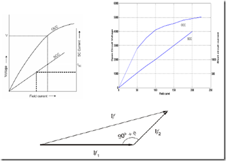
The open-circuit characteristic or magnetization curve is really the B-H curve of the complete magnetic circuit of the alternator. Indeed, in large turbo-alternators, where the air gap is relatively long, the curve shows a gradual bend. It is determined by inserting resistance in the field circuit and measuring corresponding value of terminal voltage and field current. Two voltmeters are connected across the armature terminals. The machine is run at rated speed and field current is increased gradually to If1 till armature voltage reaches rated value or even 25% more than the rated voltage. Figure 32 illustrates a typical circuit for OC and SC test and figure 33 illustrates OC and SC curve. The major portion of the exciting ampere-turns is required to force the flux across the air gap, the reluctance of which is assumed to be constant. A straight line called the air gap line can therefore be drawn as shown, dividing the excitation for any voltage into two portions, (a) that required to force the flux across the air gap, and (b) that required to force it through the remainder of the magnetic circuit. The shorter the air gap, the steeper is the air gap line.
Procedure to conduct OC test:
(i) Start the prime mover and adjust the speed to the synchronous speed of the alternator.
(ii) Keep the field circuit rheostat in cut in position and switch on DC supply.
(iii) Keep the TPST switch of the stator circuit in open position.
(iv) Vary the field current from minimum in steps and take the readings of field current and stator terminal voltage, till the voltage read by the voltmeter reaches up to 110% of rated voltage. Reduce the field current and stop the machine.
(v) Plot of terminal voltage/ phase vs field current gives the OC curve.
Short Circuit Characteristic (S.C.C.)
The short-circuit characteristic, as its name implies, refers to the behaviour of the alternator when its armature is short-circuited. In a single-phase machine the armature terminals are short-circuited through an ammeter, but in a three-phase machine all three phases must be short-circuited. An ammeter is connected in series with each armature terminal, the three remaining ammeter terminals being short-circuited. The machine is run at rated speed and field current is increased gradually to If2 till armature current reaches rated value. The armature short-circuit current and the field current are found to be proportional to each other over a wide range, as shown in Figure 33, so that the short- circuit characteristic is a straight line. Under short-circuit conditions the armature current is almost 90° out of phase with the voltage, and the armature mmf has a direct demagnetizing action on the field. The resultant ampere − turns inducing the armature emf are, therefore, very small and is equal to the difference between the field and the armature ampere − turns. This results in low mmf in the magnetic circuit, which remains in unsaturated condition and hence the small value of induced emf increases linearly with field current. This small induced armature emf is equal to the voltage drop in the winding itself, since the terminal voltage is zero by assumption. It is the voltage required to circulate the short- circuit current through the armature windings. The armature resistance is usually small compared with the reactance.
Short-Circuit Ratio:
The short-circuit ratio is defined as the ratio of the field current required to produce rated volts on open circuit to field current required to circulate full-load current with the armature short-circuited.
Short-circuit ratio = Ιf1/If2
Determination of synchronous impedance Zs:
As the terminals of the stator are short circuited in SC test, the short circuit current is circulated against the impedance of the stator called the synchronous impedance. This impedance can be estimated form the oc and sc characteristics.
The ratio of open circuit voltage to the short circuit current at a particular field current, or at a field current responsible for circulating the rated current is called the synchronous impedance.
Synchronous impedance method is easy but it gives approximate results. This method gives the value of regulation which is greater (poor) than the actual value and hence this method is called pessimistic method. The complete phasor diagram for the emf method is shown in figure 34
Ex.1. A 1200 kVA, 3300 volts, 50 Hz, three phase star connected alternator has an armature resistance of 0.25 Ω per phase. A field current of 40 Amps produces a short circuit current of 200 Amps and an open circuit emf of 1100 volts line to line. Find the % regulation at full load 0.8 pf lagging and leading by using emf method.
Ex.3. A 3-phase star connected alternator is rated at 100 kVA. On short-circuit a field current of 50 amp gives the full load current. The e.m.f. generated on open circuit with the same field current is 1575 V/phase. Calculate the voltage regulation at (a) 0.8 power factor lagging, and (b) 0.8 power factor leading by synchronous impedance method. Assume armature resistance is 1.5 Ω.
Ex. 5 The data obtained on 100 kVA, 1100 V, 3-phase alternator is : DC resistance test, E between line = 6 V dc, I in lines = 10 A dc. Open circuit test, field current = 12.5 A dc, line voltage = 420 V ac. Short circuit test, field current = 12.5 A, line current = rated value, calculate the voltage regulation of alternator at 0.8 pf lagging.
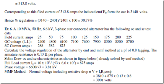
MMF method: This method is also known as amp – turns method. In this method the all the emfs produced by rotor and stator are replaced by their equivalent MMFs (fluxes), and hence called mmf method. In this method also it is assumed that the magnetic circuit is unsaturated. In this method both the reactance drops are replaced by their equivalent mmfs. Figure 35 shows the complete phasor diagram for the mmf method. Similar to emf method OC and SC characteristics are used for the determination of regulation by mmf method. The details are shown in figure 36. Using the details it is possible determine the regulation at different power factors.
 From the phasor diagram it can be seen that the mmf required to produce the emf E1= ( V + IRa) is FR1.In large machines resistance drop may neglected.
The mmf required to over come the reactance drops is (A+Ax) as shown in phasor diagram. The mmf (A+Ax) can be found from SC characteristic as under SC condition both reactance drops will be present.
Following procedure can be used for determination of regulation by mmf method.
(i) By conducting OC and SC test plot OCC and SCC as shown in figure 36.
(ii) From the OCC find the field current If1 required to produce the voltage, E1= ( V + IRa).
(iii) From SCC find the magnitude of field current If2 (≈ A+Ax) to produce the required armature current. A+Ax can also found from ZPF characteristics.
(iv) Draw If2 at angle (90+Φ) from If1, where Φ is the phase angle of current w. r. t voltage. If current is leading, take the angle of If2 as (90-Φ) as shown in figure 36.
(v) Determine the resultant field current, If and mark its magnitude on the field current axis.
(vi) From OCC. find the voltage corresponding to If, which will be E0 and hence find the regulation.
Because of the assumption of unsaturated magnetic circuit the regulation computed by this method will be less than the actual and hence this method of regulation is called optimistic method.
From OCC the field current required to produce this normal voltage is 98 amps and is represented as If1 as shown in the phasor diagram. The field current required to produce the rated current of 875 amps on short circuit is 75 amps and is drawn at an angle of 90+φ as If2 as shown. The total field current required to obtain the emf E0 is If.
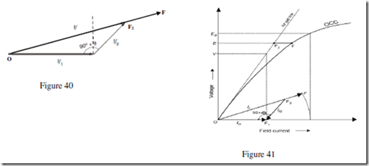
ASA Modified MMF Method: Because of the unrealistic assumption of unsaturated magnetic circuit neither the emf method nor the mmf method are giving the realistic value of regulation. In spite of these short comings these methods are being used because of their simplicity. Hence ASA has modified mmf method for calculation of regulation. With reference to the phasor diagram of mmf method it can be seen that F = FR1 – ( A+Ax). In the mmf method the total mmf F computed is based on the assumption of unsaturated magnetic circuit which is unrealistic. In order to account for the partial saturation of the magnetic circuit it must be increased by a certain amount FF2 which can be computed from occ, scc and air gap lines as explained below referring to figure 40 and 41.
If1 is the field current required to induce the rated voltage on open circuit. Draw If2 with length equal to field current required to circulate rated current during short circuit condition at an angle (90+Φ) from If1. The resultant of If1 and If2 gives If (OF2 in figure). Extend OF2 upto F so that F2F accounts for the additional field current required for accounting the effect of partial saturation of magnetic circuit. F2F is found for voltage E (refer to phasor diagram of mmf method) as shown in figure 41. Project total field current OF to the field current axis and find corresponding voltage E0 using OCC. Hence regulation can found by ASA method which is more realistic.
Zero Power Factor ( ZPF) method: Potier Triangle Method:
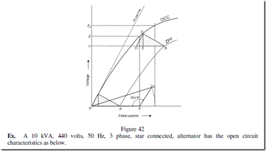
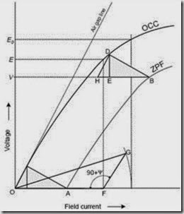
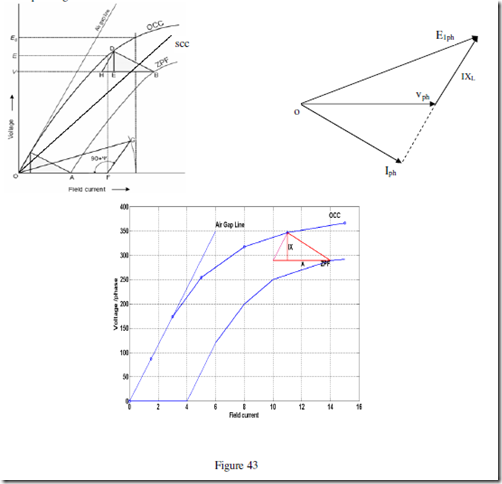
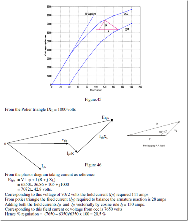
During the operation of the alternator, resistance voltage drop IaRa and armature leakage reactance drop IaXL are actually emf quantities and the armature reaction reactance is a mmf quantity. To determine the regulation of the alternator by this method OCC, SCC and ZPF test details and characteristics are required. AS explained earlier oc and sc tests are conducted and OCC and SCC are drawn. ZPF test is conducted by connecting the alternator to ZPF load and exciting the alternator in such way that the alternator supplies the rated current at rated voltage running at rated speed. To plot ZPF characteristics only two points are required. One point is corresponding to the zero voltage and rated current that can be obtained from scc and the other at rated voltage and rated current under zpf load. This zero power factor curve appears like OCC but shifted by a factor IXL vertically and horizontally by armature reaction mmf as shown below in figure 42. Following are the steps to draw ZPF characteristics.
By suitable tests plot OCC and SCC. Draw air gap line. Conduct ZPF test at full load for rated voltage and fix the point B. Draw the line BH with length equal to field current required to produce full load current on short circuit. Draw HD parallel to the air gap line so as to cut the OCC. Draw DE perpendicular to HB or parallel to voltage axis. Now, DE represents voltage drop IXL and BE represents the field current required to overcome the effect of armature reaction.
Triangle BDE is called Potier triangle and XL is the Potier reactance. Find E from V, IRa, IXL and Φ. Use the expression![]() to compute E. Find field current corresponding to E. Draw FG with magnitude equal to BE at angle (90+Ψ) from field current axis, where Ψ is the phase angle of current from voltage vector E (internal phase angle).
to compute E. Find field current corresponding to E. Draw FG with magnitude equal to BE at angle (90+Ψ) from field current axis, where Ψ is the phase angle of current from voltage vector E (internal phase angle).
The resultant field current is given by OG. Mark this length on field current axis. From OCC find the corresponding E0. Find the regulation.
Figure 42
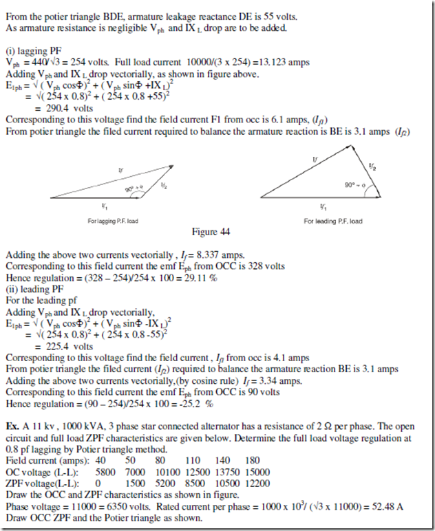
Ex. A 10 kVA, 440 volts, 50 Hz, 3 phase, star connected, alternator has the open circuit characteristics as below.
With full load zero power factor, the excitation required is 14 amps to produce 500 volts terminal voltage. On short circuit 4 amps excitation is required to produce full load current. Determine the full load voltage regulation at 0.8 pf lagging and leading.
Soln:
Draw OC, SC and ZPF characteristics to scale as shown. OC characteristics are drawn from the details given above. For sc characteristics 4 amps field current gives full load current. For ZPF characteristics two points are sufficient, one is 4 amps corresponding voltage of 0 volts, and the other is 14 amps corresponding to 500 vols.
Salient pole alternators and Blondel’s Two reaction Theory:
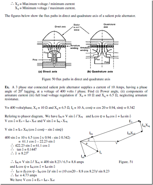
The details of synchronous generators developed so far is applicable to only round rotor or nonsalient pole alternators. In such machines the air gap is uniform through out and hence the effect of mmf will be same whether it acts along the pole axis or the inter polar axis. Hence reactance of the sator is same throughout and hence it is called synchronous reactance. But in case salient pole machines the air gap is non uniform and it is smaller along pole axis and is larger along the inter polar axis. These axes are called direct axis or d-axis and quadrature axis or q-axis. Hence the effect of mmf when acting along direct axis will be different than that when it is acting along quadrature axis. Hence the reactance of the stator can not be same when the mmf is acting along d – axis and q- axis. As the length of the air gap is small along direct axis reluctance of the magnetic circuit is less and the air gap along the q – axis is larger and hence the along the quadrature axis will be comparatively higher. Hence along d-axis more flux is produced than q-axis. Therefore the reactance due to armature reaction will be different along d-axis and q-axis. These reactances are
Xad = direct axis reactance; Xaq = quadrature axis reactance
Hence the effect of armature reaction in the case of a salient pole synchronous machine can be taken as two components – one acting along the direct axis (coinciding with the main field pole axis) and the other acting along the quadrature axis (inter-polar region or magnetic neutral axis) – and as such the mmf components of armature-reaction in a salient-pole machine cannot be considered as acting on the same magnetic circuit. Hence the effect of the armature reaction cannot be taken into account by considering only the synchronous reactance, in the case of a salient pole synchronous machine.
In fact, the direct-axis component Fad acts over a magnetic circuit identical with that of the main field system and produces a comparable effect while the quadrature-axis component Faq acts along the interpolar axis, resulting in an altogether smaller effect and, in addition, a flux distribution totally different from that of Fad or the main field m.m.f. This explains why the application of cylindrical-rotor theory to salient-pole machines for predicting the performance gives results not conforming to the performance obtained from an actual test.
Blondel’s two-reaction theory considers the effects of the quadrature and direct-axis components of the armature reaction separately. Neglecting saturation, their different effects are considered by assigning to each an appropriate value of armature-reaction “reactance,” respectively xad and xaq . The effects of armature resistance and true leakage reactance (XL) may be treated separately, or may be added to the armature reaction coefficients on the assumption that they are the same, for either the direct-axis or quadrature-axis components of the armature current (which is almost true). Thus the combined reactance values can be expressed as : Xsd = xad + xl and Xsq = xaq + xl for the direct- and cross-reaction axes respectively.
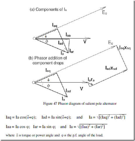
In a salient-pole machine, xaq, the quadrature-axis reactance is smaller than xad, the direct-axis reactance, since the flux produced by a given current component in that axis is smaller as the reluctance of the magnetic path consists mostly of the interpolar spaces. It is essential to clearly note the difference between the quadrature and direct-axis components Iaq, and Iad of the armature current Ia, and the reactive and active components Iaa and Iar. Although both pairs are represented by phasors in phase quadrature, the former are related to the induced emf Et while the latter are referred to the terminal voltage V. These phasors are clearly indicated with reference to the phasor diagram of a (salient pole) synchronous generator supplying a lagging power factor (pf) load, shown in Fig. 47
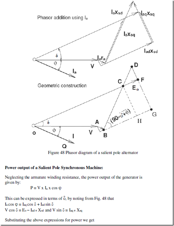
The phasor diagram Fig. 48 shows the two reactance voltage components Iaq *Xsq and Iad * Xsd which are in quadrature with their respective components of the armature current. The resistance drop Ia x Ra is added in phase with Ia although we could take it as Iaq x Ra and Iad x Ra separately, which is unnecessary as Ia = Iad + jIaq.
The above expression for power consists of two terms first is called electromagnetic power and the second is called reluctance power.
It is clear from the above expression that the power is a little more than that for a cylindrical rotor synchronous machine, as the first term alone represents the power for a cylindrical rotor synchronous machine. A term in (sin 2δ) is added into the power – angle characteristic of a non-salient pole synchronous machine. This also shows that it is possible to generate an emf even if the excitation E0 is zero. However this magnitude is quite less compared with that obtained with a finite E0. Likewise it can be shown that the machine develops a torque – called the reluctance torque – as this torque is developed due to the variation of the reluctance in the magnetic circuit even if the excitation E0 is zero.
Determination of Xd and Xq by slip test:
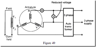
The direct and quadrature axis reactances Xd and Xq can be of a synchronous machine can be experimentally determined by a simple test known as slip test. Basic circuit diagram for conducting this test is shown in figure 49. Here the armature terminals are supplied with a subnormal voltage of rated frequency with field circuit left open. The generator is driven by a prime mover at a slip speed which is slightly more or less than the synchronous speed. This is equivalent to the condition in which the armature mmf remains stationary and rotor rotates at a slip speed with respect to the armature mmf. As the rotor poles slip through the armature mmf the armature mmf will be in line with direct axis and quadrature axis alternately. When it is in line with the direct axis the armature mmf directly acts on the magnetic circuit and at this instant the voltage applied divided by armature current gives the direct axis synchronous reactance. When the armature mmf coincides with the quadrature axis then the voltage impressed divided by armature current gives the quadrature axis synchronous reactance. Since Xd > Xq the pointers of the ammeter reading the armature current will oscillate from a minimum to a maximum. Similarly the terminal voltage will also oscillate between the minimum and maximum.
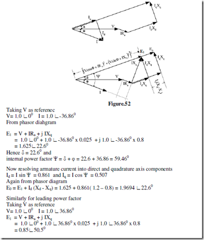
Ex. A salient pole alternator has the following per unit parameters. Xd = 1.2, Xq = 0.8, Ra = 0.025.
Compute the excitation voltage on per unit basis when the generator is delivering the rated kVA at rated voltage and a power factor of 0.8 lagging and 0.8 leading.
Soln:
The phasor diagram corresponding to the lagging power factor is shown in figure below.
Related posts:
Incoming search terms:
- phasor diagram of alternator
- why it is necessary to keep the field open while taking the reading during slip test
- determination of xd and xq of synchronous machine theory
- synchronous reactance and impedance of synchronous machines
- slip test theory
- slip test on alternator
- why Xd is greater than Xq
- in which of the following loads armature reactance is magnetizing in nature
- asa method theory
- asa method of voltage regulation pdf
- slip test on salient pole alternator ppt
- slip test on synchronous machine
- in which of the following loads armature reactance is magnetizing in nature?
- slip test on salient pole alternator
- occ and scc test of alternator
- regulation of alternator by slip test
- if Xd is d-axis synchronous reactance and Xq is q-axis synchronous reactance in a salient pole machine then
- phasor diagram of salient pole synchronous generator at leading power factor with d axis & q axis
- slip test on alternator theory
- voltage regulation of alternator by zpf method pdf
- draw the equivalent circuit of synchronous Motor
- why the o c characteristics is not linear
- to find the percentage regulation of 3-phase alternator by synchronous impedance method at various power factor and load
- in an alternator why short circuit is a straight line whereas open circuit is curve
- synchronous generator short tricks for numericals
- blondels two reaction theory
- phasor diag of syncronous motor between flux & MMF for cylinderical & salient pole rotor
- plot occ scc & zpf for syncronous generator
- pointer of ammeter and voltmeter oscillate at slip condition
- short note of power vs load angle characteristics of cylindrical rotor alternator
- circuits diagram of synchronous generator and derived impedance
- regulation of three phase alternator by using synchronous impendance method and MMF method
- draw the circuit diagram of a synchronous impedance
- A 500 kVA 2300 volt three phase star connected alternator has a full load armature-resistance drop per phase of 50 volts and a combined armature reactance plus armature-reaction drop of 500 volts per phase the percentage of voltage regulation in unity pow
- phasor diagram of salient pole alternator by lagging power factor pdf
- salient pole generator equations
- vector diagram of how regulation of alternator is affected by power factor
- what is trailing leading pole tip in synchronous machine
- why does the pointer of ammeter and voltmeter oscillate at slip condition
- how osclilogram generates in slip test for xd and xq
- obtaining power angle when solving syncronous impedance method in alternators
- pf of synchronous machine in short circuit
- quadrature axis synchronous reactance ratio is
- salient pole leading and lagging power factor
- slip test for synchronous machine
- Synchronous Generators
- what are assumptions during slip test
- asa method
- which of the following loads armature reactance is magnetizing in nature
- why filed in opem in slip trst on synchronous machine


