Developing a Wiring Diagram
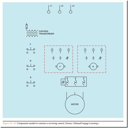
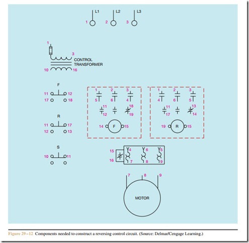
The same basic procedure is used to develop a wiring diagram from the schematic as was followed in the previous chapters. The components needed to construct
this circuit are shown in Figure 29–10. In this example, assume that two contactors and a separate three-phase overload relay are to be used.
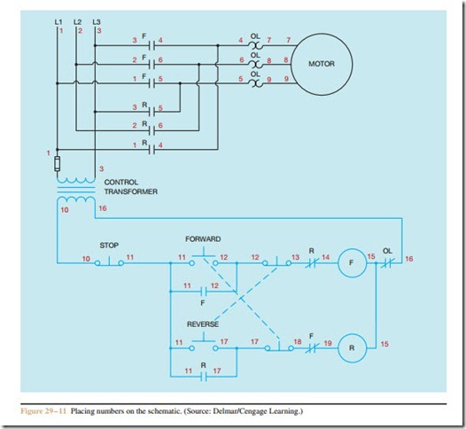
The first step is to place wire numbers on the schematic diagram. A suggested numbering sequence is shown in Figure 29–11. The next step is to place the wire numbers beside the corresponding components of the wiring diagram (Figure 29–12).
Reversing Single-Phase Split-Phase Motors
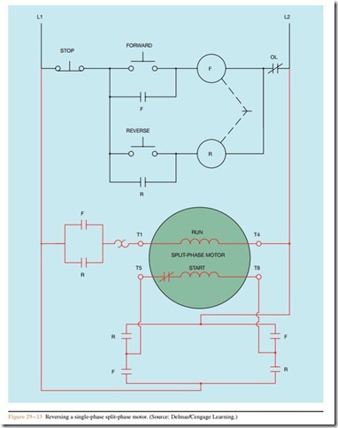
To reverse the direction of rotation of a single-phase split-phase motor, either the starting winding leads or running winding leads, but not both, are inter- changed. A schematic diagram of a forward-reverse control for a single-phase split-phase motor is shown in Figure 29–13. Notice that the control section is the same as that used for reversing three-phase motors. In this example, run winding lead T1 will always be connected to L1, and T4 will always be connected to L2. The start winding leads, however, will be changed. When the forward contactor is energized, start winding lead T5 will be connected to L1, and T8 will be connected to L2. When the reverse contactor is energized, start winding lead T5 will be connected to L2, and T8 will be connected to L1.
Review Questions
1. How can the direction of rotation of a three-phase motor be changed?
2. What is interlocking?
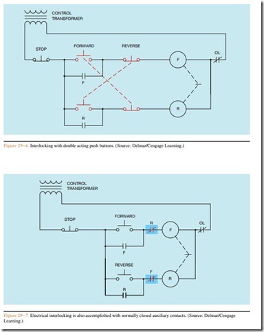
3. Referring to the schematic shown in Figure 29–7, how would the circuit operate if the normally closed R contact connected in series with F coil were connected normally open?
4. What would be the danger, if any, if the circuit were wired as stated in question 3?
5. How would the circuit operate if the normally closed auxiliary contacts were connected so that F contact was connected in series with F coil,
and R contact was connected in series with R coil, Figure 29–7?
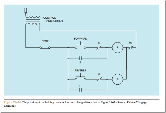
6. Assume that the circuit shown in Figure 29–7 were to be connected as shown in Figure 29–14. In what way would the operation of the circuit be different, if at all?
Related posts:
Incoming search terms:
- single phase forward reverse control circuit
- single phase motor forward reverse wiring diagram
- motor control circuit diagram forward reverse pdf
- single phase motor with capacitor forward and reverse wiring diagram
- single phase motor wiring diagram forward reverse
- forward reverse motor control circuit pdf
- forward reverse motor control using relay
- forward reverse single phase motor control circuit
- forward reverse switch wiring diagram
- reverse forward motor control circuit diagram
- reversing single phase motor wiring diagram
- single phase forward reverse wiring diagram
- motor control circuit diagram forward reverse
- single phase motor reverse forward connection
- forward reverse single phase motor wiring diagram
- single phase induction motor forward reverse connection diagram
- automatic forward and reverse control circuit
- forward reverse single phase motor diagram
- schematic diagram of forward reverse motor control
- forward and reverse ac-motor circuit
- forward reverse motor wiring diagram
- single phase forward and reverse motor
- single phase forward and reverse
- forward reverse motor control circuit diagram
- single phase motor forward reverse
- single phase forward reverse diagram
- single phase forward reverse switch
- forward reverse with limit switch diagram
- forward reverse starter control circuit
- forward reverse starter
- forward reverse starter circuit diagram single phase
- single phase forward reverse
- l&t automatic rotate swetches
- reverse forward control circuit diagram
- electric motor wiring diagram forward reverse
- reverse forward starter
- forward reverse switch single phase motor
- forward reverse switch connection diagram
- Reverse Forward Control diagram
- forward reverse motor control circuit
- forward reverse wiring diagram
- drawing of the forward revise
- forward reverse single phase motor
- forward reverse motor starter
- Autotransformer mail
- single phase electrical motor winding diagram download
- forward reverse starter theory
- reverse forward diagram
- Reverse forward starter diagram
- 3phash motar startar canection daigram hd