AIR PUMP SYSTEMS
American Motors Air Guard, Chrysler Air Injection, Ford Thermactor & GM Air Injection Reactor (A.I.R.)
This system is used to reduce carbon monoxide and hydrocarbon emissions by adding a controlled amount of air to the exhaust gases through the ex haust ports. This causes oxidation of gases and an appreciable reduction of carbon monoxide and hydrocarbon emissions.
All air pump systems, Figs. 7 and 8, consist of an air injection pump, air injection tubes (one for each cylinder), a mixture control or backfire by pass valve (added in 1966, ’67), a diverter or air by-pass valve (added in 1968), check valves (one for in-line engines, two for V-8 engines), air mani folds, pipes and hoses necessary to connect the various components.
Carburetors and distributors for engines with an air pump system are designed especially for these engines, and they should not be interchanged with or replaced by carburetors or distributors for en
gines without the air pumps.
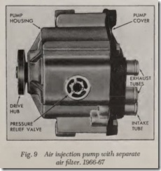
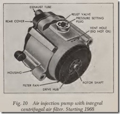
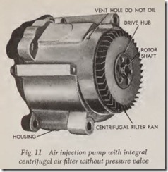
The air injection pump, Figs. 9, 10 and 11, com presses the air and injects it through the air mani folds, hoses and injection tubes into the exhaust system in the area of the exhaust valves. The fresh air ignites and burns the unburned portion of the exhaust gases, thus minimizing the noxious con tent of the exhaust.
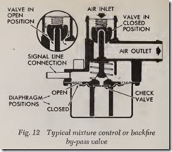
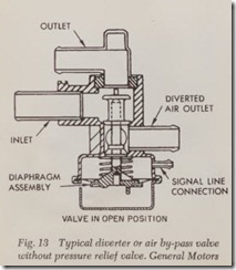
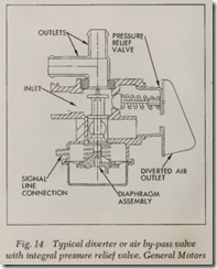
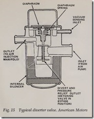
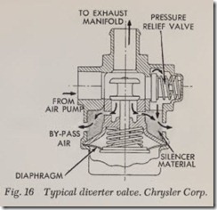
The mixture control or backfire by-pass valve, Fig. 12, when triggered by a sharp increase in man ifold vacuum, as when the throttle is suddenly closed, supplies the intake manifold with fresh filtered air to lean out the fuel-air mixture and prevent exhaust system backfire.The diverter or air by-pass valve, Figs. 13, 14, 15 and 16, when similarly triggered by a sharp in crease in manifold vacuum, shuts off the injected air to the exhaust ports and helps to prevent back firing during this period when the mixture is ex ceptionally rich. During engine overrun, all the air from the pump is dumped through the muffier on the diverter or air by-pass valve. At high engine speeds, the pump produces more air than the engine can use, and the excess is dumped through the pressure relief valve when that valve is part of the air pump, Figs. 9 and 10, or through the di verter or air by-pass valve when the pressure re lief valve is part of that valve, Fig. 14.
The check valve or valves prevent exhaust gases from entering and damaging the air injection pump, as back flow can occur even under normal operating conditions.
When properly installed and maintained, the system will effectively reduce exhaust emissions. However, if any system components or any engine component that operates in conjunction with the air pump system should malfunction, exhaust emissions might increase.
Because of the relationship between engine operating condition and unburned exhaust gases, the condition of the engine and tune-up should be checked whenever the air pump system seems to be malfunctioning. Particular care should be taken in checking items that affect fuel-air ratio, such as crankcase ventilation system ( PCV), the carbure tor and carburetor air cleaner.
Air Switching Valve
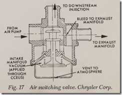
This valve, Fig. 17, is used on 1977 Chrysler Corp. vehicles to switch air injection from the ex haust ports to an injection point further down stream in the exhaust system after engine warm-up so that air injection will not offset the effect on NOx emissions by the EGR.
When the engine is warming up and NOx emis sions are low, air injection to the exhaust ports is acceptable, however, as the gases become hotter they tend to oxidize more rapidly by the addition of secondary air causing an increase of NOx emis sions. At his time, the air switching valve switches the air injection.
A vacuum signal from the CCEVS causes the switching valve to open allowing all air injection into the exhaust ports. When CCEVS shuts off vacuum to the switching valve, the valve closes and bypasses most of the air injection to the in jection point downstream in the exhaust system. A bleed hole in the switching valve permits a small amount of air pump air to be injected into the exhaust ports at all times to assist in CO and HC reduction.
Power Heat Control Valve
This valve is used on 1977 Chrysler Corp. vehicles to increase the flow of hot exhaust gases through the lef t-hand exh aust manif old to rapidly bring the mini- catalyst up to operatin g tempera ture . The CCEVS controls the manifold vacuum signal necessary to activate the valve. At coolant temperatures below a predetermined level, mani f old vacuum is applied to the valve and all exhaust gases flow through the left hand exhaust manifold. Above this tempera ture n o vacuum is applied to the valve and exhaust gas flows throu gh both the right and left exhaust m anif olds.
Vacuum Differential Valve (VDV)
On 1975-77 Ford vehicles with the Thermactor system and catalytic converters, a VDV Fig. 18, is used to control the oper ation of the air bypass valve. Under normal operation, vacuum applied through the VDV holds the valve upward , block ing the vent port and allowing Therma ctor air flow. During acceleration or deceleration or in case of system failure, the VDV momen tarily cuts off vacuum flow to the bypass valve, diverting the Thermactor air flow to atmosphere. In case of ex cessive pressure or system restriction, the excess pressure will unseat the valve in the lower part of the bypass valve, allowing a partial flow of air to atmosphere. At the same time, the valve in the up per part of the valve remains unseated allowing a partial flow of air to the exhaust manifold.
The VDV, Fig. 19, used on Chevrolet Chevette models is located in the air by-pass valve vacuum signal line and is used to prevent backfire in th e exhaust system by direoting the air bypass valve to divert the air pump output to atmosphere under high vacuum conditions. A sudden rise in intake manifold vacuum during deceleration perio ds ereates a vacuum condition under the VDV dia phragm to pull the vacuum dump valve disc down and interrupt the vacuum signal to air bypass valve by diverting the vacuum source to atmo sphere. Elimination of vacuum to the air bypass valve causes diversion of air pump output to atmo sphere for about 2 seconds. The timing orifice hole in the VDV equalizes the vacuum pressure on both sides of the diaphragm allowing the valve to re turn to its normal position and permitting vacuum continuity in the air bypass valve signal line.
Differential Vacuum Delay & Vacuum Separator Valve
This valve, used on Chevrolet Chevette models, is located in series with the VDV in the vacuum signal line to the air bypass valve. The differential vacuum delay and separator valve aids in control of vehicle exhaust emissions by delaying diversion of the air from the air bypass valve during hard accelerations from 16-30 seconds. This is accom plished by the air bleed restrictions which allow only gradual reduction in the vacuum trapped in the signal line by the check valve.
During steady engine operation where there is no vacuum change to close the check valve, a constant .01 cubic foot per minute of filtered under hood air is drawn through the restrictors to purge the signal line below the check valve of all fuel and contaminants.
During deceleration when manifold vacuum in creases, the pressure differential across the check valve causes it to open, thus immediately allow ing the vacuum differential and air bypass valve to be controlled by the increasing vacuum.
Differential Valve Delay Valve (DVDV)
This delay valve, used on some 1975-77 vehicles, delays air by-pass during periods of low engine manifold vacuum. During sudden drops in mani fold vacuum, DVDV delays operation of vacuum differential valve ( VDV). A sudden raise in mani fold vacuum will open check in delay valve.
Exhaust Check Valve
This valve, used on some 1975-77 vehicles, allows Thermactor air to enter exhaust port drillings, but prevents reverse flow of exhaust gases in event of improper operation of system components. This valve is located between by-pass valve and exhaust port drillings, either on air manifold or engine.
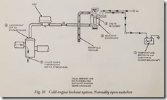
Cold Engine Lockout System
This system is used on 1975-77 Ford vehicles with the Thermactor system and catalytic convert ers. It consists of an electrically operated vacuum solenoid in the vacuum circuit to the by-pass valve and temperature sensors in the air cleaner housing and floor pan ( on some models ) .
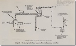
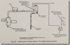
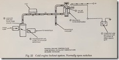
Two different type systems are used. The first type consists of normally closed switches that pro vide current to the solenoid only when the engine is warm. The second type consists of normally open switches that provide current to the solenoid only when the engine is cold. Operation of both systems is as follows:
Normally Closed Switches, Type 1, Figs.20 & 21
With engine at normal operating temperature and all components operating properly, electrical path is provided through the solenoid vacuum valve, air cleaner sensor, floor pan temperature sensor (on some models) and to ground. This pro vides vacuum flow through the vacuum solenoid valve, VDV and to the bypass valve, allowing Thermactor air flow.
If any of the switches should operate due to low intake air temperature or overheated floor pan (on some models), the vacuum solenoid will stop vacuum flow, causing the bypass valve to divert Thermactor air to atmosphere.
Normally Open Switches, Type 2, Figs. 22 & 23
With engine at normal operating temperature and all components operating properly, the sole noid vacuum valve is inoperative, thereby pro viding vacuum flow through the solenoid vacuum valve, VDV and to the bypass valve, allowing Thermactor air flow. With the engine cold, the air cleaner sensor operates, providing current flow through the solenoid vacuum to ground. If the floor pan sensor operates (on some models), it will provide current flow through the solenoid to ground.
If the solenoid vacuum valve operates, it stops the vacuum flow to the bypass valve, causing the Thermactor air flow to be diverted to atmosphere.
Maintenance
Engine tune-up should be checked whenever the air pump system seems to be malfunctioning, especially items affecting air/fuel ratio.
Because of the similarity of many parts, typical illustrations and procedures are given in the fol lowing text.
Air Manifold, Hose and Tube, Fig. 24
1. Inspect all hoses for deterioration or holes.
2. Inspect all tubes for cracks or holes.
3. Check all tube and hose routing for interfer ence that may cause wear.
4. Check all hose and tube connections.
5. If a leak is suspected on the pressure side of the system, and any tubes and/or hoses have been disconnected on the pres sure side, the connections should be checked f or leaks with a soapy water solution . With the pump run ning, bubbles will form at any leak.
6. To replace any hose or tube, note the routing, then remove the hoses or tubes as required.
Note that the hoses used with this system are made of special material to with stand high tem perature. No other type of hose should beused .
![Fig. 7 Typical installation of an air pump system with a mix¬_thumb[1] Fig. 7 Typical installation of an air pump system with a mix¬_thumb[1]](http://machineryequipmentonline.com/electric-equipment/wp-content/uploads/2020/06/Fig.-7-Typical-installation-of-an-air-pump-system-with-a-mix%C2%AC_thumb1_thumb.jpg)
![Fig. 8 Typical installation of an air pump system with a diverter_thumb[1] Fig. 8 Typical installation of an air pump system with a diverter_thumb[1]](http://machineryequipmentonline.com/electric-equipment/wp-content/uploads/2020/06/Fig.-8-Typical-installation-of-an-air-pump-system-with-a-diverter_thumb1_thumb.jpg)
![Fig. 18 Vaccum differential valve. 1975-77 Ford with Thermactor and_thumb[1] Fig. 18 Vaccum differential valve. 1975-77 Ford with Thermactor and_thumb[1]](http://machineryequipmentonline.com/electric-equipment/wp-content/uploads/2020/06/Fig.-18-Vaccum-differential-valve.-1975-77-Ford-with-Thermactor-and_thumb1_thumb.jpg)
![Fig. 19 Vacuum differential valve (VDV). 1976_thumb[1] Fig. 19 Vacuum differential valve (VDV). 1976_thumb[1]](http://machineryequipmentonline.com/electric-equipment/wp-content/uploads/2020/06/Fig.-19-Vacuum-differential-valve-VDV.-1976_thumb1_thumb.jpg)
![Fig. 24 Typical air manifold installations_thumb[1] Fig. 24 Typical air manifold installations_thumb[1]](http://machineryequipmentonline.com/electric-equipment/wp-content/uploads/2020/06/Fig.-24-Typical-air-manifold-installations_thumb1_thumb.jpg)