Flow Sensors
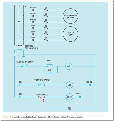
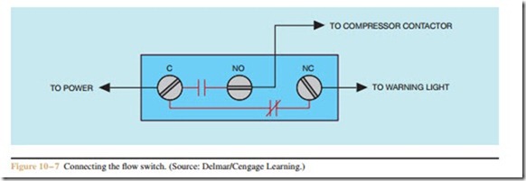
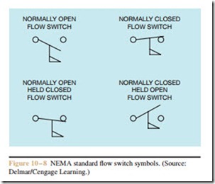
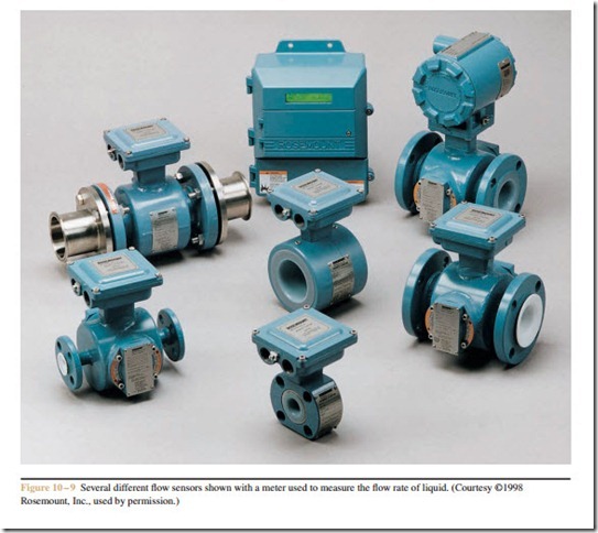
low current loads such as contactor or relay coils or pilot lights. A circuit that employs both the normally open and normally closed contact of a flow switch is shown in Figure 10 – 6. The circuit is designed to control the operation of an air compressor. A pressure switch controls the operation of the compressor. In this circuit, a normally open push button is used as a reset button. The control relay must be energized before Flow switches are used to detect liquid flowing through a pipe or air flowing through a duct. Flow switches, however, cannot detect the amount of liquid or air flow. To detect the amount of liquid or air flow, a transducer must be used. A transducer is a device that converts one form of energy into another. In the case of a flow sensor, the kinetic energy of a moving liquid or gas is converted into electrical energy. Many flow sensors are designed to produce an output current of 4 to 20 milliamperes. This current can be used as the input signal to a programmable controller or to a meter designed to measure the flow rate of the liquid or gas being metered (Figure 10 – 9).
Electromagnetic Flow Sensors
Another type of flow sensor is the electromagnetic flow sensor. These sensors operate on the principle of Faraday’s Law concerning conductors moving through a magnetic field. This law states that when a conductor moves through a magnetic field, a voltage will be induced into the conductor. The amount of induced volt- age is proportional to the strength of the magnetic field and the speed of the moving conductor. In the case of the electromagnetic flow sensor, the moving liquid is the conductor. As a general rule, liquids should have a minimum conductivity of about 20 microhms per centimeter.
Flow rate is measured by small electrodes mounted
Liquid Flow Sensors
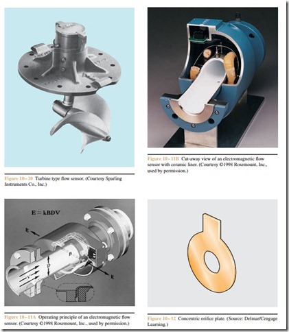
There are several methods that can be used to measure the flow rate of a liquid in a pipe. One method uses a turbine type sensor (Figure 10 – 10). The turbine sensor consists of a turbine blade that must be inserted inside the pipe containing the liquid. The moving liquid causes the turbine blade to turn. The speed at which the blade turns is proportional to the amount of flow in the pipe. The sensor’s electrical output is determined by the speed of the turbine blade. One disadvantage of the turbine type sensor is that the turbine blade offers some resistance to the flow of the liquid.
inside the pipe of the sensor. The electrodes measure the amount of voltage induced in the liquid as it flows through the magnetic field produced by the sensor (Figure 10 – 11A). Since the strength of the magnetic field is known, the induced voltage will be proportional to the flow rate of the liquid. A cut-away view of an electromagnetic flow sensor with a ceramic liner is shown in Figure 10 – 11B.
Orifice Plate Flow Sensors
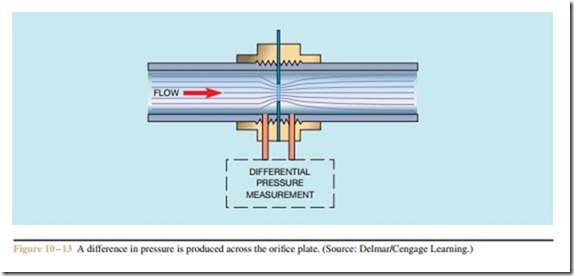
Orifice plate flow sensors operate by inserting a plate with an orifice of known size into the flow path (Figure 10 – 12). The plate is installed between two special flanges (Figure 10 – 13). The flanges are constructed to permit a differential pressure meter to
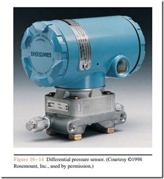
be connected across the plate. When liquid flows through the orifice, a difference of pressure is produced across the plate. Since the orifice is of known size, the pressure difference is proportional to flow rate. It is the same principle as measuring the voltage drop across a known resistance to determine the amount of current flow in a circuit. The disadvantage of the orifice plate sensor is that it does add restriction to the line. A differential pressure sensor is shown in Figure 10 – 14.
Vortex Flow Sensors
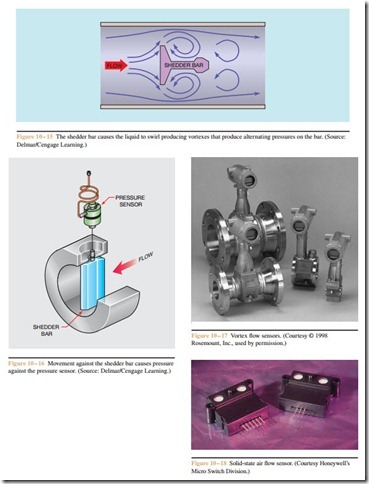
Vortex flow sensors operate on the principle that when a moving liquid strikes an object, a swirling current, called a vortex, is created. Vortex sensors insert a shedder bar in the line to produce a swirling current or vortex (Figure 10 – 15). This swirling current causes the shedder bar to alternately flex from side to side. The shedder bar is connected to a pressure sensor that can sense the amount of movement of the shedder bar (Figure 10 – 16). The amount of movement
of the shedder bar is proportional to the flow rate. Several different sizes of vortex flow sensors are shown in Figure 10 – 17.
Airflow Sensors
Large volumes of air flow can be sensed by prop- driven devices similar to the liquid flow sensor shown in Figure 10 – 10. Solid-state devices similar to the one shown in Figure 10 – 18 are commonly used to sense smaller amounts of air or gas flow. This device operates on the principle that air or gas flowing across a surface causes heat transfer. The sensor contains a thin-film thermally isolated bridge with a heater and temperature sensors. The output voltage is dependent on the temperature of the sensor surface. Increased air flow through the inlet and outlet ports will cause a greater amount of heat transfer, reducing the surface temperature of the sensor.
Review Questions
1. What are typical uses of flow switches?
2. Draw a line diagram to show a green light that will glow when liquid flow occurs.
3. Draw a one-line diagram showing a bell that will ring in the absence of flow. Include a switch to turn off the bell manually.
4. What is a transducer?
5. What is the most common output current for flow sensors?
6. What is Faraday’s Law concerning conductors moving through a magnetic field?
7. What type of flow sensors use Faraday’s Law as their principle of operation?
8. What is the operating principle of the solid-state air flow sensor described in this text?
