AUTOMATIC TRACKING SYSTEM
The Video 8 format uses a more advanced form of head-tracking control called Automatic Track Finding (ATF). This system relies on the fact that at relatively low recording frequencies the azimuth offset of the two video heads is not effective in preventing crosstalk from tracks adjacent to the one being scanned.
The principle is to add to the video signal being recorded a pilot tone at the very low end of the tape-frequency spectrum. A different pilot tone is used on successive tracks in a carefully chosen sequence: 101 kHz, 117 kHz, 163 kHz and 147 kHz. The sequence then repeats over successive groups of four tracks – frequencies given here are approximate. The track layout is shown in Fig. 13.6(a). During replay the ATF tones are read off the tape and separated from the video signals in a low-pass filter. When the correct track is being scanned
by the appropriate head the most prominent ATF frequency is that coming from the track being read. There are, however, vestiges of crosstalk signals from both adjacent tracks, and each of these beats with the main ATF signal to give two new frequencies: examination of Fig. 13.6(a) shows that for any given track the beat frequencies are either (in round figures) 46 kHz (e.g. crosstalk appearing on track 3 output from adjacent track 4) or 16 kHz (i.e. crosstalk appearing on track 3 output from adjacent track 2). The ATF frequencies are carefully chosen to ensure that this is so, see Fig. 13.6(b). Continuing with track 3 as our example, an increase in 46 kHz beat output indicates that the head-scan is straying too high, whereas an increase in 16 kHz beat output indicates that the head-scan is too low. When the 16 kHz and 46 kHz beat products are balanced in level the replay head must be exactly centred on its intended track. The situation is reversed for line 2: a predominance of 16 kHz output warns of too high a head-path, a predominance of 46 kHz output is the result of too low a head-path. Again, when both crosstalk signals are equal the head is correctly aligned on track 2.
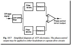
Processing of the ATF replay signals is illustrated, in basic form, in Fig. 13.7. The heads’ output signals, after low-pass filtering, are applied to two sharply tuned acceptor circuits, one resonant at 16 kHz, the other at 46 kHz. Each feeds its own amplitude detector, whose outputs are in proportion to the respective crosstalk levels. Adding the outputs gives an error signal whose polarity indicates the direction of the tracking error, and whose amplitude indicates the magnitude of the tracking error. After amplification the error signal is applied as a phase-control to the capstan or head-drum motor to maintain accurate tracking.
The loop works continuously to maintain equal crosstalk signals from both adjacent tracks, thus ensuring optimum tracking without the need for any form of user control; tolerances due to non- standard recordings, tape tension, temperature and ageing are automatically taken up. In Video 8 LP mode the video tracks are a mere 17 microns wide, and such a narrow track can only be reliably scanned with the aid of an ATF system. In VHS systems a simpler form of auto-tracking is used in many machines: the level of off- tape f.m. signal is continuously monitored, or sampled at the begin- ning of play, or when the user presses a key. Tracking is adjusted electronically to maximise the replay signal. In this closed-loop system a continuously variable user tracking control is thus unnecessary.

