CAMERA SECTION BLOCK DIAGRAM
Fig. 6.11 shows the processing stages in a video/TV camera or the camera section of a camcorder. Starting at the left, the lens has two drive motors, for zoom and focus. The former is under user control via a rocker switch or in/out keys. The focus lens is also adjustable by the user, either directly or via the focus motor in a servo loop. In auto-focus mode the focus motor servo loop is driven by a microprocessor-controlled section, here based on the sharpness of the luminance signal waveform. Two filters are placed in front of the
CCD image sensor: an infra-red-cut type to prevent the image being affected by heat and below-visible wavelength emission from the subject in view; and a ‘crystal’ filter which limits the image definition (spectral response) to forestall interference and ‘beat’ effects in the televised image. The CCD sensor is driven and serviced by its drive chip, from which it receives the drive and transfer pulses described earlier in connection with Figs 5.17 and 5.18.
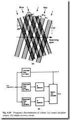
The luminance path is similar to that shown in Fig. 6.3, though here the luminance Y signal passes directly to the recording electron- ics as well as to an encoder to provide an E−E (Electronics to Electronics) composite signal at the camcorder’s video-out socket. In this design the mosaic filter on the sensor faceplate is made of magenta/cyan/yellow/green dots, permitting a relatively simple colour recovery system on a 2-line basis. Initially the chroma signals are separated off by the two sample-and-hold detectors working on SP1 and SP2 pulses from the CCD driver. Auto white balance (see below) is carried out by a dedicated microprocessor using the video signal itself, with gain-correction being carried out via the amplifiers in the chrominance process circuit. Colour separation into B−Y and R−Y signals is based on the use of a 64 μs delay line, a double-pole, double- throw electronic switch and an inverting amplifier, here shown on the right of the diagram. On their way to the recording section of the camcorder – and the PAL encoder – titles, composed by the user, are added.
This camcorder does not use resistive or capacitative presets in its camera (or most other) sections. Instead each process is set up and controlled by data stored in an EEPROM and distributed as a serial datastream; the commands are D−A converted on the spot. More details of this control technology are given in Chapter 22.
Digital image processing
Although digital (DVC format) camcorders will be discussed in Chapter 19, it is more convenient to deal here with those analogue- format (derivatives of VHS and 8 mm) video cameras which use digital processing in their signal paths. Immediately after the CCD- sensor signal has been filtered and a.g.c.-controlled it is converted to a 10-bit (Y + C) or 8Y + 8C digital datastream. Inside a ‘camera- core’ chip all the necessary processing – contour-enhancement, white- balance, gamma-correction, encoding etc. – is carried out entirely in the digital realm, producing (after D−A conversion and filtering) Y and C signals for passage to the recording deck and PAL encoder. The process is governed by a microprocessor.
Digital zoom and ‘steady-shot’
The incorporation of a complete digital field memory store, whether or not the signal processing is based on digital techniques, permits two useful features: digital picture zoom and camera-shake compensation. Picture zoom is achieved by scanning the field memory area selectively, i.e. confining the real-time readout to a small area of the image field store. By this means individual pixels are ‘blown-up’ to give the effect of magnification, though it does not enlarge detail in the same way as optical zoom.
If the picture written into the field store is made larger than is required to fulfil the camera’s definition and optical specifications, an anti-shake feature can be provided by providing pitch (vertical) and yaw (horizontal) motion sensors within the camera body. Their outputs, representing G-forces, are used to control the memory-read address-generators in such a way as to provide shake-compensation, encroaching into the normally masked ‘margins’ of the picture- memory area as necessary. The same effect is achieved by similar means in other designs by providing a larger-than-necessary image sensor chip and having the motion sensors govern the timing of the ‘scan’ pulses from the CCD-drive IC to float the read-out picture about, within limits, on the surface of the image-sensor itself.
Early forms of anti-shake technology involved a physical correc- tor in the shape of an oil-filled bellows-effect prism lens inside the optical block. These artifices have become necessary as camcorders have shrunk in size and weight and been given longer zoom lenses: the human hands that hold them tend to tremble, one of the many physiological factors for which technology has to cater.

