OFDM demodulation
You will recall that in the OFDM system, a large number of carriers (1705 and 6817 carriers in the 2K and 8K modes, respectively) are used. Each carrier is phase modulated by a symbol consisting of 4 bits (16-QAM) or 6 bits (64-QAM). The purpose of the demodulator is to retrieve the 4-bit or 6-bit data represented by the phase shift of the carriers. The basic principles of the OFDM demodulator are illustrated in Figure 18.8. Following digitisation of the low IF baseband by the ADC, original OFDM carriers are reconstructed
using a fast Fourier transform (FFT) processor which analyses the incoming signal into its frequency components. The QAM-modulated OFDM carriers are then fed into a mixer.
Let’s consider the operation with one OFDM carrier. The mixer is fed with two signals: an OFDM carrier and local oscillator signal of equal fre- quency, fc. The output from the mixer is the sum and difference of the two frequencies. If the OFDM carrier contains no phase shift, an output signal with a beat frequency of 2fc will be obtained. However, if the OFDM car- rier is phase modulated, the phase angle will be produced at the output together with the 2fc beat signal.
This is explained mathematically as follows:
The task of the demodulator is to separate the phase angle from the twice- carrier frequency signal. The obvious way of doing this is to use a filter. While this is possible for one carrier, it is not practical for several thousand, as is the case with the OFDM technique. The process is further complicated by the fact that each local oscillator frequency will beat with all the other OFDM carrier frequencies, producing millions of beat frequencies of differ- ences and sums. A technique has to be devised to remove all beat signals and leave only the phase shift angles. This is where the integrator comes in using the fact that the integral of a sine wave is the area under the sine wave curve and thus the integral of a sine wave over one complete cycle is zero; there is as much area above the zero line as below it. The same applies over a 2-cycle period and so on. Provided we integrate a sine wave over a complete num- ber of cycles, the result will always be zero. Going back to the OFDM system, the spacing between the carriers is a precise figure, namely 4464 Hz for the 2K mode and 1116 Hz for the 8K mode. Every carrier is therefore a multiple of 4464 or 1116 as appropriate. Thus, if the baseband signal is integrated over
one cycle of the carrier spacing (1/4464 = 224 fls or 1/1116 = 896 fls for the 2K and the 8K modes, respectively), all the carriers will be reduced to zero. The only element left would be the phase shift of each carrier which represents the transmitted data. The process is repeated for each set of modulated carriers.
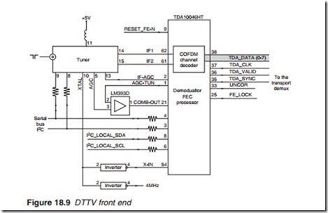
A typical DTTV front end is shown in Figure 18.9. The tuner receives a UHF signal from the aerial and produces two IF signals: IF1 and IF2 which are fed to the COFDM demodulator/FEC processor TDA10046HT. The demod/FEC chip is a multi-standard package incorporating its own micro- processor and carry out all necessary functions including demodulation, deinterleaving and error correction to extract the original bitstream. The output is an 8-bit transport stream (TDA DATA 0–7) together with a number of control signals: transport clock (TDA_CLK), data valid (TDA_VALID), sync (TDA_SYC), drop uncorrected data (UNCOR) and bit clock (FE_LOCK). Both the tuner and the demod/FEC are controlled by an I2C bus. The functional block diagram of the COFDM demodulator/FEC TDA10046HT chip is shown in Figure 18.10.


