Television receivers CRT-type
In the previous chapters, we described the various types of display devices from the traditional CRT to the plasma, LCD and the latest DLP rear- projection. The next few chapters will consider the technology involved in receiving and processing video signals in preparation for display.
There are several ways in which a video signal may be received for pro- cessing. These include the traditional analogue TV broadcasts as well as the current digital television. Video signals may also be received from a variety of video equipments such as DVD players, VCRs and set-top-boxes via a variety of connections such as SCART, S-video and HDMI. This chapter will cover terrestrial analogue television using a CRT display unit.
The analogue TV receiver
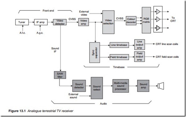
The basic functional units of an analogue terrestrial television receiver are shown in Figure 13.1.
The tuner selects the UHF carrier frequency for the TV channel as chosen by the user and converts it to an intermediate frequency (IF) of 39.5 MHz. The modulated IF is then amplified through several stages of amplification and demodulated to obtain the original composite video, blanking and sync (CVBS) signal. The CVBS signal is then separated into its three component parts: video, sound and sync.
The video selection switch (sometimes inappropriately called video processor) selects one of the video signal for further processing as chosen by the user. The video in the form of CVBS from the video selector is fed to the colour decoder to reproduce the original RGB (or YUV) signals which fol- lowing the RGB matrix, are fed to the CRT via individual RGB amplifiers. The 6-MHz sound inter-carrier is taken off at the video detector stage using a surface acoustic wave (SAW) filter. The FM sound signal is detected, ampli- fied and fed into the loudspeaker via the sound select chip. The sync pulses are clipped from the video information at the video output stage, separated into line and field, and taken to the appropriate timebase. After amplifica- tion, line and field pulses are used to deflect the electron beam in the hori- zontal and vertical directions via a pair of scan coils.
Automatic gain control (a.g.c.) is employed to ensure that the output of the IF stage remains steady irrespective of changes in the strength of the received signal. The a.g.c. performs three basic functions in a TV receiver.
First, it enables the switching over from a strong channel to a weaker one, or vice versa, without having to adjust the receiver. Second, it avoids over- loading the RF/IF amplifying stages which would introduce severe dis- tortion. Third, it attempts to reduce the flutter caused by reflections of transmitted signals from moving objects such as airplanes. The effective- ness of flutter reduction depends on the time constant of the a.g.c. circuit. Automatic frequency control (a.f.c.) is sometimes used to keep the IF stable at 39.5 MHz.
Apart from providing the drive for the line scan coils, the line output stage also provides the extra high tension (e.h.t.) for the c.r.t. by the use of an overwind at the line output transformer (LOPT) as was mentioned in Chapter 9. The line output stage is also used to provide other stabilised d.c. supplies for the receiver.
