U and V separation
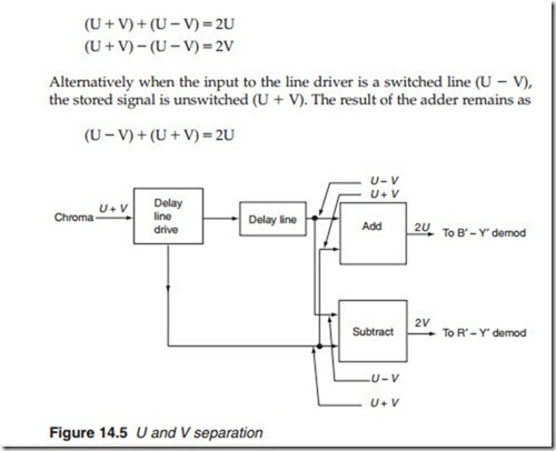
Figure 14.5 shows how the PAL-D system separates the U and V components; the chrominance signal of the previous line is stored or delayed for one line duration (64 f.s for PAL and 63.59 f.s for NTSC). The delayed sig- nal is then added to and subtracted from the signal of the current line to produce separate U and V signals. The precise value of the required delay is very slightly less than one line duration; this is because the number of cycles per line always ends with a half cycle and the delay must correspond to a whole number of sub-carriers.
Let us assume that the chrominance signal going into the delay line driver in Figure 14.5 is unswitched, i.e. U + V. The chrominance signal at the output of the delayed line is that of the preceding line, i.e. switched line U – V. Addition of the two signals gives
But the subtraction is reversed (U – V) – (U + V) = –2V The U and V separator thus retains the phase reversal of the V component and also removes the phase error.
