Temporal compression
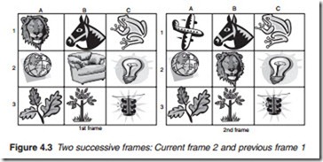
Temporal compression, or inter-frame compression, is carried out on successive frames. It exploits the fact that the difference between two successive frames is very slight. Thus, it is not necessary to transmit the full contents of every picture frame since most of it is merely a repetition of the previous frame. Only the difference needs to be sent out. Two components are used to describe the difference between one frame and the preceding frame: motion vector and difference frame. To illustrate the principle behind this technique, consider a sequence of two frames shown in Figure 4.3. The contents of the cells in the first frame are scanned and the contents are described as follows: lion, horse, frog, globe, chair, bulb, leaves, tree and traffic lights. The second frame is slightly different from the first and if described in full in the same way as the first frame: plane, horse, frog, globe, lion, bulb, leaves, tree and traffic lights.
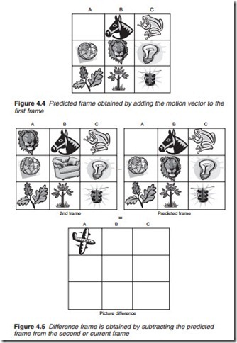
However, such an exercise involves a repetition of most of the elements of the first frame, namely horse, frog, globe, bulb, leaves, tree and traffic lights. The repeated elements are known as redundant because they do not add anything new to the original composition of the frame. To avoid redundancy, only the changes of the contents of the picture are described instead. These changes may be defined by two aspects: the movement of the tiger from cell A1 to cell B2 and the introduction of a plane in cell A1. The first is the motion vector. The newly introduced plane is the difference frame and is derived by a slightly more complex method. First the motion vector is added to the first frame to produce a predicted frame (Figure 4.4).
The predicted frame is then subtracted from the second frame to produce the difference frame (Figure 4.5). Both components (motion vector and frame difference) are combined to form what is referred to as a P-frame (P for predicted).
Group of pictures
Temporal compression is carried out on a group of pictures (GOP) normally composed of 12 non-interlaced frames. The first frame of the group (Figure 4.6) acts as the anchor or reference frame known as the I-frame (I for inter). This is followed by a P-frame obtained by comparing the second frame with the I-frame. This is then repeated and the third frame is compared with the previous P-frame to produce a second P-frame and so on until the end of the group of 12 frames when a new reference I-frame is then inserted for the next group of 12 frames and so on. This type of prediction is known as forward prediction.
Block matching
The motion vector is obtained from the luminance component only by a process known as block matching. Block matching involves dividing the Y component of the reference frame into 16 X 16 pixel macroblocks, tak- ing each macroblock, in turn, moving it within a specified area within the next frame and searching for matching block pixel values (Figure 4.7). Although the sample values in the macroblock may have changed slightly
from one frame to the next, correlation techniques are used to determine the best location match which is down to a distance of one half-pixel in the case of MPEG-2 and quarter-pixel in the case MPEG-4. When a match is found, the displacement is then used to obtain a motion compensation vector that describes the movement of the macroblock in terms of speed and direction (Figure 4.8). Only a relatively small amount of data is necessary to describe a motion compensation vector. The actual pixel values of the macroblock themselves do not have to be retransmitted. Once the motion compensation vector has been worked out, it is then used for the other two components, CR and CB. Further reductions in bit count are achieved using differential encoding for each motion compensation vector with reference to the previous vector.


