Colour signals in the VCR
If we had a perfect video tape recorder, there would be no reason why we could not take the composite video signal, chrominance and all, and record it on the tape as an FM signal, demodulate it during replay and recreate the original video signal as described for luminance in the first part of this chapter. As we’ve already seen, a home VCR is far from per-ect in its performance, and the direct recording idea will not work for two good reasons.
The bandwidth limitations of our VCRs have already been described, and with an upper cut-off frequency around 3.5 MHz, the colour signals at 4.43 MHz are left out in the ‘cold’ somewhat! Even in S-VHS format, whose signal passband approaches 5 MHz, it is still not possible to directly record an encoded colour signal. Because the VCR relies on mechanical transport, perfectly smooth motion cannot be achieved. Inevitable imper- fections in bearing surfaces and friction drives the elasticity of the tape and minute changes in tape/head contact all combine to impart a degree of timing jitter to the replayed signal. In good audio tape systems, this jit- ter is imperceptible, and for luminance replay its effects can be overcome by the use of timebase correctors in professional machines, or fast-acting TV line-synchronising systems with domestic VCRs. The latter class of machine, in good condition, may be expected to have a timing jitter of about 20 fls over one 20 ms field period. Let’s examine the effect of this on the chrominance signal.
We have seen that the hue of a reproduced colour picture depends entirely on the phase of the sub-carrier signal. ‘Phase’ really means rela- tive timing, so if the timing of the sub-carrier signal relative to the burst is upset, hue errors will appear. One cycle of sub-carrier occupies 226 ns, and a timing error of this order will take the vector right round the ‘clock’ of Figure 21.28, passing through every other hue on the way! A timing error of 100 ns (one ten-millionth of a second) will turn a blue sky into a lime- green one, and the jitter present in a mechanical reproduction system will make nonsense of the colours in the picture. For acceptable results, sub- carrier phase errors need to be held within 5° or so, representing a per- missible maximum timing jitter of ±3 ns as shown in Figure 21.29. The physical causes of jitter cannot be eliminated so an electronic method of sub-carrier phase correction is necessary. To achieve this, the luminance and chrominance signals are separately treated (Figure 21.30).
Let’s first examine the problem posed by the high-colour sub-carrier frequency. Several solutions are possible, including decoding the chromi- nance signal to baseband (i.e. primary colour or colour-difference signals) before committing them to tape, then recoding them to PAL standard
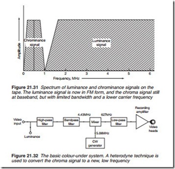
during the replay process. This would require a lot of circuitry, and be vul- nerable to hue and saturation errors. A better solution is to keep the PAL- encoded signal intact, bursts, phase modulation and all, and merely convert it to a suitable low frequency for recording. During playback, the composite chrominance signal can be re-converted to the normal 4.43 MHz carrier for recombination with the luminance component into the standard form of colour video signal, compatible with an ordinary TV set.
Space has to be found for the colour signal in the restricted tape fre- quency spectrum, however, and it is made available below the luminance
sideband, where a gap is purposely left in the 0–1 MHz region. This area is kept clear by tailoring the luminance record passband and the FM mod- ulator deviation to avoid luminance sidebands falling into it during colour recording. The colour signal, then, is down-converted and bandwidth- limited so that it occupies a frequency band of roughly 0–1 MHz. It is a double-sideband signal, so that the carrier frequency needs to be centred on about 500 kHz and the sidebands limited to 500 kHz or so. The spec- trum of the down converted signal known as the colour-under signal is shown in Figure 21.31; compare this with Figure 21.26.

