Response time
Response time is one of the few areas remaining where the performance of a traditional CRT still holds an advantage over LCD displays. CRTs have nearly instantaneous pixel response times, but LCDs tend to be much slower. The result is the user might see smearing, motion blur or other visual artefacts when there is movement on the screen.
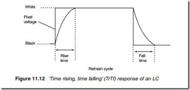
A pixel’s response time is the time it takes a pixel to change state. If it is a rise-and-fall response, then it is a measure of the time it takes a pixel to change state from black-to-white-to-black as illustrated in Figure 11.12. More specifically, it represents the pixel ability to change from 10% ‘on’ to 90% ‘on’ and then back from 10% ‘off’ to 90% ‘off’ again. Originally, this was the standard way of reporting response times of LCD TVs and com- puter monitors, and was normally listed as a TrTf (time rising, time falling) measurement. Some manufactures started using a grey-to-grey (GtG) meas- urement for LCD response times which is different from TrTf. There are as yet no standards and manufacturers can state any figure that suits them.
One factor that affects the response time is the viscosity of the LC mate- rial. This means it takes a finite time to re-orientate its molecules in response to a changed electric field. A second factor is that the capacitance of the LC material is affected by the molecule re-alignment which changes the TFT load and with it the brightness to which the cell ultimately settles.
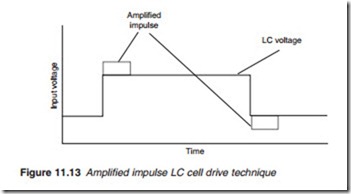
A good response time starts at around 25 ms with some LCD TV man- ufacturers claiming a response time as fast as 16 ms or less. Short response times are required for fast moving images such as games. New techniques have been developed to reduce the response time. Such techniques include the use of lower viscosity LC material. Reducing the cell gap thickness is another technique which results in fewer LC material to re-orientate giving a response time as little as 8 ms. Thinner cells make production more difficult with lower yields and hence more expensive. Another technique apply a drive signal for a brief duration in order to give the pixel cells a ‘jump start’ and then reducing it to the required level as illustrated in Figure 11.13. This technique known as amplified impulse provides grey- to-grey transition to be completed up to five times faster than a typical LC display.
For TV images, two techniques have been developed, both attempt to hide the cell transition time. ‘Backlight strobing’ involves flickering the backlight off momentarily and the ‘black frame insertion’ introduces a black frame during the LC transition. Backlight strobing also helps improve motion blur caused by the ‘sample-and-hold’ effect in which an image when held on the screen for the duration of a frame-time, blurs the retina as the eye tracks the motion from one frame to the next. By comparison, when an electron beam sweeps the surface of a cathode ray tube, it lights any given part of the screen only for a miniscule fraction of the frame time. It’s a bit like comparing film or video footage shot with low- and high-shutter speeds. This type of motion-blur has come about as manufacturers moved from the traditional resistor type digital-to-analogue converter (DAC) to the much more compact sample-and-hold type. Motion blur originating
from sample-and-hold in the display can become less of an issue as the frame rate is increased.

