DARK CURRENT AND LAG
The performance of the vidicon tube is limited by two main factors: its dark current and its lag. In theory no current should flow when no illumination is present at the target; in practice a small random current is present to cause shading and noise (grain) on the dark parts of the reproduced picture, and reduce the dynamic range (contrast gamut) of the picture.
Image lag is a phenomenon whereby an ‘image’ is retained on the target when the light stimulus itself has gone. Its effect is to produce comet-tails on fast-moving objects or when the camera is panned across a scene, especially at low light levels. In this respect the true vidicon (antimony trisulphide target) is very poor, and the development of other types of tube, particularly the Plumbicon, improved lag performance by a factor of ten. For some types of tube a weak uniform background light applied to the target, typically from a red LED (Light-Emitting Diode) in the optical system or communicat- ing with the target via a lightpipe from the base region of the tube, gives an improvement in performance. It is used to establish a uniform reference dark current, maintaining beam/target contact at all times to avoid a ‘detail drop-out’ effect in the dark areas of the picture under all electron-beam conditions; and increasing the required target potential to a point where image lag is almost eliminated.
COLOUR SENSING WITH A SINGLE TUBE
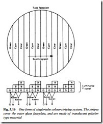
The photoconductive pick-up tube responds basically to the bright- ness (luminance) component of incoming light, and provided that the tube is reasonably panchromatic (sensitive to all colours) in its response the target’s output signal is suitable, after amplification and insertion of sync pulses, for r.f. modulation or direct feed to a video monitor. To produce a colour picture more information must be generated by the image sensor – enough in fact to give details of the nature of all three of the primary colours, red, green and blue at every single picture element. Techniques have been developed to achieve this with a single photoconductive tube, involving some form of matrixed faceplate. One variant is the colour striped faceplate drawn in Fig. 5.16.
In this form of striped faceplate the outer surface of the vidicon’s front glass is covered with vertical stripes of translucent colour filters in the form green, cyan, clear, green, cyan, clear, and so on. The green filter will permit only the green (G) component of incoming light to pass; the adjacent cyan filter lets through both blue (B) and green (G) components; the clear stripes, of course, pass all light allowing red (R), G and B to reach the vidicon’s photosensitive target. The basic video signal from the tube’s target electrode produces a luminance signal, since the image being scanned still contains all brightness information for the scene being televised. Because of the presence of the stripes, however, an extra signal will now appear at the target, modulated with information concerning the colours in the scene.
As the faceplate is scanned, each line of picture information contains ‘steps’ as shown at the bottom of Fig. 5.16. The first step contains the G signal, the secondaB+G signal, and the third an R +B+G signal. If we subtract the G signal from the B+G signal we have a B signal. Subtraction of the B + G signal from the R + B + G signal renders an R signal. Thus by a simple matrix circuit we can derive the three primary colour signals (RGB) required for a colour TV system, ultimately for the three guns of a shadowmask picture tube. While this simple explanation proves that three primary colours can be derived from a stripe-filter using only two colours, green and cyan, the way in which the chroma signal is derived and processed in a practical camera is different, making full use of the luminance signal produced at the target: these techniques will be described in the next chapter.
The pitch of the stripes in the colour filter is in the region of 40 μm, so the vidicon’s beam focusing requirements are very stringent. As soon as the beam diameter exceeds the stripe width all colour is lost, and deterioration of beam focus will remove the colour (and in some cameras, substitute an overall green cast to the picture) long before any loss of fine detail (luminance response) is discernible.
Fine detail in the picture being televised would cause a ‘beat’ pat- tern against the colour stripe gratings, so an optical filter (crystal filter) is present in the light path to remove it. This is one reason why very expensive lens systems are wasted on this type of camera. Because most types of vidicon tube – and particularly the Newvicon – are sensitive to infra-red radiation, an IR filter is also fitted: without this the colour rendering of an object would depend on its temperature as well as its natural colour.
