De-gamma correction and error and diffusion
Unlike the CRT, the relationship between the input signal and the bright- ness obtained from a FPD is linear and since a gamma correction is introduced at the broadcasting stage to compensate for the CRT’s non-linear relationship, a de-gamma correction is necessary if the signal is to be fed into a panel. The dither and error diffusion circuits are used to reduce the effect of quantising error which results in a tendency to loose grey scales.
Digital video interface
Direct connection between the processing section and the panel requires a large number of connectors, all carrying high-frequency signals (24 con- nections for video, three or more connectors for vertical and horizontal syncs and clocks and numerous earth connections). Among other draw- backs, direct connection is susceptible to electromagnetic interference (EMI). For this reason, the preferred method of connecting the processing section to the panel assembly is the use of DVI.
One of the problems of transferring data at a high bit rate is the band- width requirement. For instance, a 24-bit, 640 X 480 resolution video with a refresh rate of 50 Hz requires 640 X 480 X 24 X 50 = 368.64 Mbps and for a resolution of 1280 X 1024 resolution video at a refresh rate of 50 Hz would demand a staggering 1280 X 1024 X 24 X 50 = 1.57 Gbps.
The normal RS-422, RS-485, SCSI and others have limitations in terms of bandwidth and interference making them unsuitable for use as connec- tors to an LCD, plasma or DLP displays. Hence the need for an interface that is capable of such data rates with low power requirements and low interference. This is what the DVI specifications provide. There are two main types of DVIs: DVI-D for digital only and DVI-I for both digital and analogue signals.
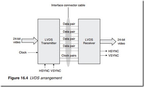
There are four established techniques: low-voltage differential signalling (LVDS), PanelLink and TMDS) and for high-definition video high-definition multimedia interface (HDMI). In all cases, differential data transmission is used. This is because unlike the single-ended schemes, it is less susceptible to common-mode noise. Noise coupled on the interconnect is seen as a common-mode modulation by the receiver and is rejected. In a single-ended combination Figure 16.3a, noise in the form of a spurious pulse would affect the ‘live’ wire only, appears at the receiving end and is amplified like the actual wanted signal. However, if a differential signalling is used in which a pair of wires carry signals of opposite polarities, common-mode noise affects both wires equally appearing in the same polarity on both of the wires. When they are subtracted at the receiving end to obtain the signal, they cancel out, a process known as common-mode rejection.
