Signal processing and control
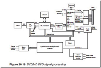
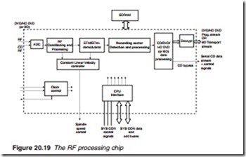
Figure 20.18 shows the principle units involved in the signal processing of a DVD/HD DVD playback system. The OPU, generates the laser beam with the appropriate wavelength and detects the reflected beam using a number of photodiodes to produce two types of signals: a varying signal representing pit and lands on the surface of the disc, known as the RF and a number of error signals used for the servo control system. All these sig- nals are fed into the RF amplifier. The RF amplifier performs two distinct functions on the incoming signals. It amplifies the RF signal to a level suit- able for processing by the next stage and carries out digital processing of the error signals for the servo DSP. The RF signal is fed to the RF processor which carries out the following functions:
● RF signal processing including de-multiplexing to extract the various video, audio and other PES packets.
● Clock sync extraction
● EFM+ (16/8) demodulation Frame/sector sync detection Error correction
The process of demultiplexing the PES packets requires a memory bank to store the PESs as they arrive to allow the RF processor to select and
re-arrange them in the required order. Before audio and video decoding, the PES stream has to be descrambled to return it to the original bit sequence. Following that, the PES packets are sent to the multi-standard A/V decoder chip which carries out the decoding of the video, audio and sub-picture packets into digitised analogue video and pulse code modulated audio signals. Decoding compressed video involves data de- compression and the reconstruction of the video stream, picture by picture from the I frames and the P and B frames. The process of decoding thus requires a memory bank to store the I, P and B frames for reconstruction of actual frames to take place. A similar process takes place in the case of decoding compressed audio information. The memory bank also serves as a 1 s audio delay for lip-sync. This delay is necessary since the decoding of the video packets takes a longer time than the decoding of audio infor- mation. The A/V DRAM memory chip provides this memory bank. Digital video and audio PCM is fed to a HDMI encoder/transmitter for the HDMI output port. Analogue audio and video are also available for SCART, S-video and component video. Audio PCM together with control signals L/R, bit clock and sampling clock are fed to an audio digital signal processor (DSP) for conversion into a digitised audio output.
The whole process is programmed and controlled by a powerful micro- processor centred on a system control (sys con) chip with an embedded RISC microprocessor core. Sys con carries all necessary programming and control of signal and servo processing. It incorporates data, address and control bus structure together with a FLASH memory store. It provides a serial control bus for controlling such units as the audio DSP as well as the user interface.
The FLASH memory is a non-volatile RAM chip used to store start-up and other initialising and processing routines. One of the functions of the sys con chip is to ensure that the correct track sector is read at the correct speed and with correct focus. This is carried out by the servo DSP chip. The final part of the player is the user interface which is managed by the interface control to provide the necessary interface between the player and font panel control buttons, front panel display and remote control handset.

