SDTV sampling rate
The analogue video waveform contains the video information together with line sync pulses. Only the video information needs to be digitised and converted into a video bitstream. As was described earlier in Chapter 1, of the total 64 J.s period of one line of a PAL composite video, 12 J.s are used for the sync pulse, the front porch and the back porch leaving 52 J.s to carry the video information. With 720 pixels per line,
This would be the sampling frequency if sampling was to start at the end of one sync pulse and finish at the start of the next. However, to allow for analogue drift, sampling is extended to a period slightly longer than the active line duration. In this way, sampling begins just before the end of a sync pulse and ends just after the start of the next sync pulse. For this reason, a fre- quency lower than 13.8 MHz is necessary. A sampling rate of 13.5 MHz was thus selected to satisfy this as well as other criteria. One of these is that the sampling rate must be divisible by line frequency: 13.5 = 864 X 15.625 for PAL and 858 X 15.734 for NTSC. The number of active pixels per line is therefore = 13.5 X 52 = 702 for PAL and 13.5 X 52.6 = 710 pixels for NTSC.
The other criterion for adequate sampling is the Nyquist rate. This states that to ensure that the reconstructed waveform contains all of the information of the original analogue waveform, the minimum sampling rate must not be less than twice the highest frequency of the analogue input. This is known as the Nyquist rate. In practice, the sampling rate is chosen to be 10–12% higher than the Nyquist rate to cater for the inevitable slope of the filter’s cut-off curve. With a nominal maximum video frequency of 6 MHz for SDTV, the Nyquist rate is 2 X 6 = 12 MHz. The chosen sampling rate of 13.5 MHz is 12.5% higher than the Nyquist rate. For HDTV, a sampling frequency of 74.25 MHz which is 5.5 X 13.5 MHz is chosen to cater for the increased number of pixels per line. More on this in later chapters.
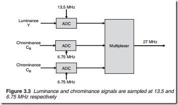
As outlined in Chapter 1, colour TV broadcasting involves the transmis- sion of three components: luminance Y and colour differences CR = R – Y and CB = B – Y. In the analogue TV system, the luminance is transmitted directly using amplitude modulation (terrestrial broadcasting) or fre- quency modulation (satellite broadcasting). For the chrominance compo- nents, quadrature amplitude modulation is used with a colour subcarrier of 4.43 MHz. In DVB, the three components are independently sampled, converted into three digital data streams before compression, modulation and subsequent transmission. For the luminance signal, which contains the highest video frequencies, the full sampling rate of 13.5 MHz is used. As for the chrominance components CR and CB, which contain lower video frequencies, a lower sampling rate or subsampling is acceptable. CCIR (Comite Consultatif International Radiocommunication) recommends a subsampling rate of half that used for the luminance rate, i.e. 0.5 X 13.5 = 6.75 MHz. Following the multiplexer where all three streams are com- bined into a single stream, a total sampling rate of 13.5 + 6.75 + 6.75 = 27 MHz is obtained which is known as the system clock (Figure 3.3).

