The standard colour bar display
There have been several test displays since the TV broadcasting began; among them is one of the more important namely the colour bar. A stan- dard colour bar waveform produces eight vertical bars of uniform width which include three primary colours, three complementary colours, black and white in the following order:
White Yellow Cyan Green Magenta Red Blue Black
On a monochrome receiver this is known as the grey scale display shown in Figure 2.14 with peak white on the left of the screen followed by grey stripes changing in luminance growing progressively darker from left to right. The luminance steps are not uniform as illustrated by the video waveform in Figure 2.15.
The waveforms of the primary components red, green and blue of the colour bar display are shown in Figure 2.16a together with the chromi- nance signal in (b). When the chrominance signal (b) is added to the grey scale waveform (c), the standard colour bar waveform in (d) is obtained.
Gamma-correction
In a cathode ray tube, the beam current represents the brightness of the display. Changes in brightness are produced by changes in the voltage between the cathode and the grid of the tube and with it the beam current.
This relationship is non-linear and if not corrected, severe deterioration in the quality of the picture will result. This non-linearity at the receiving end is compensated by the introduction of an equal and opposite non-linearity at the transmitting end; it is known as gamma-correction (y-correction). The voltage E from the camera is raised to a power of l/y (i.e. E1/y), where for UK TV transmission y = 2.2 and l/y = 0.45. Gamma-corrected signals are indicated using a prime, e.g. Y’, R’ and gamma-corrected colour dif- ference signals are indicated as Y’- R’ and Y’- B’.
Weighting factors
The subcarrier has maximum amplitude when 100% or fully saturated colour is transmitted. Since the subcarrier is added to the luminance sig- nal, the amplitude of the composite colour signal may exceed the maxi- mum possible voltage. To avoid this, the peak amplitude of the chrominance signal, i.e. the peak amplitude of the colour difference sig- nals, is reduced by a factor known as the weighting factor. The new weighted components of the chrominance signal are called U and V where
U = 0.493(B¢ – Y¢) V = 0.877(R¢ – Y¢)
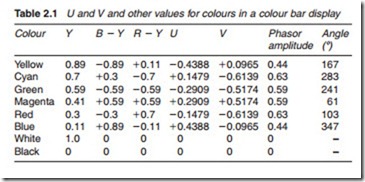
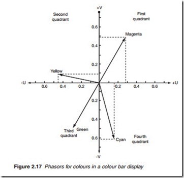
The resultant chrominance phasor is now produced by the phasor sum of U and V. The values of U and V and their respective phasors representing a colour bar display is shown in Table 2.1 and Figure 2.17, respectively, and Figure 2.18 shows the expected waveforms for the colour difference signals.
PAL colour system
There are three main systems of colour transmission: NTSC, PAL and SECAM (sequential colour with memory). All three systems split the
colour picture into luminance and chrominance; all three use colour dif- ference signals to transmit the chrominance information. The difference between them lies in the way in which the subcarrier is modulated by the colour difference signals. SECAM (used in France, Russia, Eastern Europe and parts of Africa) transmits the colour difference signals U and V on alternate lines: U on one line, V on the next, and so on. The other two sys- tems, NTSC (used mainly in North and Central America, parts of South America, Japan and south east Asia) and PAL (used in the UK, western Europe with the exception of France, Asia, most of Africa, Australia and New Zealand), transmit both chrominance components simultaneously using QAM.
However, it is found that, due to a phase shift either in the transmission path or in the receiver itself, the relative phases of the chrominance signal and the colour subcarrier burst suffer a change in the form of phase delay or advance (Figure 2.19). This effect, known as differential phase distor- tion, can be quite severe, and to counter it, NTSC receivers are fitted with a hue control with which the phase of the subcarrier generator can be adjusted to somewhere near the correct axis, as subjectively judged on
flesh-tones. This is somewhat haphazard, and certainly inconvenient, as hue adjustment is often necessary on channel-changing.
Such errors are almost completely corrected by the PAL system. With PAL, the V signal is reversed line by line, V on one line followed by -V on the next, and so on, hence the name ‘Phase Alternate Line’. The first line is called an NTSC line and the second line is called a PAL line. Phase errors are thus reversed from one line to the next. At the receiving end, a process of averaging consecutive lines by the eye cancels out the errors to repro- duce the correct hue. This simple method is known as PAL-S. A more accurate method is the use of a delay line to allow for consecutive lines (NTSC and PAL) to be added to each other, thus cancelling phase errors physically. This is known as PAL-D.
In order to distinguish between the two types of lines, the colour burst is made to change its phase by approximately 180, as an NTSC line is followed by a PAL line and back again. For this reason, the PAL colour burst is known as the swinging burst in the PAL system.


