NTSC colour components
In the NTSC 525-line system, the two colour difference signals, I and Q, are given different bandwidths. For Q, double sideband is used with a bandwidth of ±400 kHz. For the I component, vestigial sideband is used with a bandwidth of 400 kHz for the upper sideband and 1.3 MHz for the lower sideband. This reduced bandwidth is a direct result of the reduced NTSC channel bandwidths. Figure 2.11 illustrates the frequency components of the 525-line NTSC system as used in the USA showing the 3.58 MHz colour subcarrier and the I and Q chrominance components.
NTSC refresh rate
It was stated in Chapter 1 that the 60 Hz nominal refresh rate for NTSC has been slightly modified to 59.94 Hz. This came about with the introduction of colour television. In an NTSC broadcast, the vision carrier is amplitude modulated by the video signal as described above, while sound is trans- mitted by frequency modulating a carrier 4.5 MHz higher. If the video sig- nal is affected by non-linear distortion, the 3.58 MHz colour carrier may beat with the sound carrier to produce a dot pattern on the screen. To min- imise this and avoid any interference between the chrominance signal and the audio carrier, the original 60 Hz field rate was adjusted down by the factor of 1000/1001, to 59.94059 fields per second.
When the modulated subcarrier is added to the luminance (monochrome) signal to form the composite colour signal, the modulated subcarrier appears as a sine wave superimposed on the monochrome signal; it changes in amplitude and phase. The amplitude of the subcarrier repre- sents saturation. Thus a fully saturated colour is represented by maximum subcarrier amplitude; black and white is represented by zero subcarrier amplitude. Hue, by contrast, is represented by the phase angle of the sub- carrier. A typical waveform is shown in Figure 2.12.
Colour burst
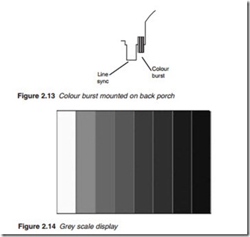
To ascertain the phase angle of the chrominance signal and therefore hue, a ‘burst’ of about 10 cycles of the original subcarrier is transmitted for use as a reference at the receiver. This colour burst is mounted on the back porch of the line sync as shown in Figure 2.13. At the receiving end, the phase of
the modulated colour signal is compared with the phase of the regenerated subcarrier to provide a measure of the phase angle and therefore hue. The absence of a colour burst indicates a black and white transmission.

