AUDIO RECORD AND PLAYBACK
Except for the Video 8 system, the analogue video formats were originally designed for use with longitudinal sound tracks written onto and read off the tape by a stationary head assembly fitted between the head drum and the pressure roller. The techniques used are identical to those employed in audio tape recording, except that the tracks are much narrower (1 mm wide) and the linear speed of the tape is low, varying from 2.4 cm/s to 1.17 cm/s in various formats and modes. The narrow audio tracks are not capable of better S/N ratio than about 43 dB, or 50 dB with sophisticated noise-reduction systems. The low linear tape speed sets an upper frequency limit of about 10 kHz in normal modes and 6 kHz in LP modes. Wow and flutter is typically 0.25% w.r.m.s.
While this standard of performance is adequate for time-shifting of serial programmes and for use with TV sets having small loudspeakers, its shortcomings become obvious when the videorecorder is used with high-quality input signals and good reproduction equipment. In programmes where sound is an important feature (mainly concerts and feature films) the longitudinal sound system early became a considerable drawback to the well-established formats. The consumer’s awareness and appreciation of high-fidelity sound has been brought about by the long availability of good quality sound tuners, amplifiers and loudspeakers, and by compact audio disc systems and the provision of Hi-Fi amplifiers and stereo loudspeakers in TV receivers and ‘unit’ systems.
A solution to the problems of longitudinal sound recording can- not be found in further development of the basic system; the limitations are in the nature of the tape’s magnetic layer, and in the physical wavelengths of the frequencies involved: they are immovable within the constraints of available videotape track-width and speed. A more promising approach is to record sound in the helical tracks used for video, where it has the benefits of high writing speed and (provided signal-conditioning and a modulation system is used) a high S/N ratio and wide dynamic range. Three different methods of achieving this have been evolved for use in consumer videorecorders: Depth- Multiplex, Frequency Multiplex and PCM, which stands for Pulse Code Modulation. These will be described in turn.
DEPTH MULTIPLEX
The principle of depth multiplex recording is illustrated in Fig. 17.1, and depends on the use of separate heads for the audio and video f.m. carriers. In Fig. 17.1(a) the drum-mounted audio and video heads are moving towards the right in record mode. Generally there is an optimum relationship between the wavelength of the signal recorded on the tape and the depth (d) of its penetration into the tape’s surface, expressed as d = λ/4. For the audio Hi-fi head the gap is cut wide (0.7 or 1 micron) and a relatively low f.m. carrier frequency around 1.6 MHz is used for recording. The result is that the audio signals penetrate deep (about 4 microns) into the tape’s magnetic coating. Following closely behind the audio head comes the video head, writ- ing higher-frequency signals with a smaller head gap. In this case pattern depth d is about 0.7 micron, and so a shallow pattern is recorded – the down-converted chroma signals have too low a recording current to achieve greater depth during record. The top layer of the depth-audio magnetic pattern is thus erased by the recording action of the video head, to be replaced by a shallow ‘pool’ of video pattern. During replay the presence of the over-recorded video track
attenuates the replayed audio signal by 12 dB or so, but the use dur- ing record of an f.m. modulation system and high writing current for the audio carrier overcomes this.
The two audio signals are modulated onto separate carriers for pas- sage through the head/tape interface – for VHS the carrier frequencies are 1.4 MHz (stereo left) and 1.8 MHz (stereo right) each with a maximum deviation of ±150 kHz. Significant sidebands extend the total audio f.m. bandwidths to over 500 kHz each, as shown in Fig.
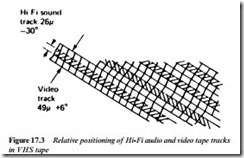
17.2. Plainly there is potential here for mutual crosstalk between f.m. sound and f.m. video carriers during playback. To prevent it the audio Hi-Fi head gaps are given large offset azimuth angles of ±30°. Except in VHS-LP mode it is also arranged that the audio and video heads which share one track are given opposite azimuth angles so that the track-pattern disparity becomes 36° since the video heads are at ±6°. The Hi-Fi sound heads are mounted at a large angle to the video heads around the spinning drum. The angle varies between different makes and designs and matters only from the points of view of (a) correct ‘height’ mounting of audio heads to ensure that the relative placement of video and audio tracks is correct; and (b) correct timing of the audio-head changeover point during playback with reference to the head tacho-pulse. Synchronisation between vision and
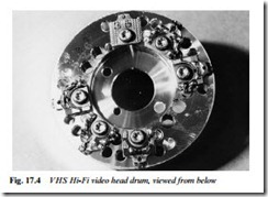
sound is not relevant where the passage of half the drum circumference only occupies 20 ms. For VHS the width of each f.m. audio track is 26 microns, about half of that of the corresponding video track. The ‘buried’ audio track lies centrally beneath the video track as shown in Fig. 17.3. The photo (Fig. 17.4) shows a Hi-Fi drum assembly. The ‘head’ at 12 o’clock position is a blank, included to confer physical balance. Counting clockwise from it are video head 1, audio head 1, a flying erase head (at six o’clock position), video head 2, audio head 2. The audio Hi-Fi heads have a rotary transformer to themselves, with separate sections for each, either above or below the drum, and electrically and magnetically isolated from the vision rotary transformer. Both f.m. carriers are fed to each head during record, even though only one head at a time is actually scanning the tape and writing L and R f.m. carriers onto the tape. During replay, head switching at 20 ms intervals is used to maintain continuity of output signal, as per standard video head practice. The two f.m. carriers are separated by bandpass filters during the replay process, then individually dealt with.
Hi-Fi audio recording
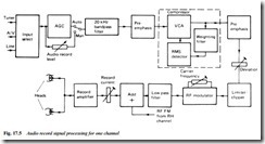
As with the video signal, a large amount of conditioning is required by the audio signal in its preparation for f.m. recording, and in its restoration during playback. Fig. 17.5 is a simplified block diagram of the processing of the left-hand audio signal during record – the right-hand channel is identical, and their two f.m. signals are added
in the ‘+‘ block at the bottom centre of the diagram. First comes an input select matrix to route the required audio input from line, AV or TV tuner sources. A choice of manual or automatic level control is provided, the former by a front panel slider control and the latter by an a.g.c. circuit. The level-corrected signal now enters a bandpass filter wherein its upper range is restricted to 20 kHz, or 15 kHz in some designs to avoid trouble from TV line timebase radiation and stereo pilot tones which may be present in the audio input signal. This filter prevents excessive sideband generation by the f.m. modulator further downstream. A degree of pre-emphasis is now applied to the signal before it enters the compressor stage, which forms the heart of the Hi-Fi sound recording system.
The effect of the compressor is shown on the left-hand side of Fig. 17.6(a). A total dynamic range of 80 dB in the incoming audio signal is compressed to 40 dB for recording on tape in a logarithmic amplifier/attenuator whose gain or loss is determined by the amplitude of the audio signal itself. The latter is closely monitored in a true-r.m.s. detector, whose output is applied as a control potential to the voltage-controlled amplifier/attenuator (VCA). The logarithmic law by which it operates is shown on the graph of Fig. 17.6(b): at standard (0 dB) level the signal is unaffected. For every 60 mV increase of ‘raw’ signal 10 dB of attenuation is applied, and for every 60 mV decrease of raw signal (from 0 dB) 10 dB of gain is applied – the derivation of Fig. 17.6(a) is now clear. What neither diagram of Fig. 17.6 shows is the frequency selective nature of the
compressor, introduced by incorporating a weighting filter in the path to the r.m.s. detector. The filter has a rising characteristic above 1 kHz, which has the effect of further compressing high-frequency components in the final output signal, and permitting more effective pre-emphasis in the pre-modulator stage without the risk of over- deviation in the f.m. modulator. The record compressor stage is built into a purpose-designed IC, along with the r.m.s. detector and associated circuitry, while filtering is catered for in external RC networks. Returning to Fig. 17.5, the pre-emphasis stage which follows the
compressor has a rising response between 2 kHz and 20 kHz, follow- ing normal noise-reduction technique in f.m. modulation systems – during replay a filter with opposite characteristic will be used to restore spectrum-balance and reduce tape noise in so doing. The pre- emphasised audio signal next encounters a preset gain control with which its amplitude (hence deviation of the audio f.m. modulator) is set. Accidental over-deviation is prevented by a clipper stage.
signal is generated by an IC-based voltage-controlled oscillator (VCO). As with the vision modulator stage it is basically an astable circuit depending for basic timing on an RC network, part of which is made adjustable for the purpose of carrier frequency- setting; in the case of Fig. 17.5, which illustrates the stereo-left channel of a VHS machine, it is adjusted for 1.4 MHz with zero audio input. The harmonics of the astable output signal reach up to high frequencies and (to prevent interference with luminance carriers and sidebands) are removed by an LC bandstop filter with sharp cut-off beyond 1.65 MHz.
After the low-pass filter the left-channel f.m. carrier signal is joined by a similar signal coming from the stereo-right modulating circuit and based on 1.8 MHz. Together they pass through a gain control (audio f.m. writing current set) en route to a class B push-pull power amplifier stage similar to that used for head-driving in the video recording stage. The two audio f.m. carriers have equal writing cur- rent.
Hi-Fi audio replay
The functions of the individual blocks in the audio replay chain of Fig. 17.7 generally mirror those used in record. First come a pair of sensitive head preamplifiers fed from the two audio rotating trans- formers. Their outputs are sequentially selected by an electronic head switch operating in accordance with a delayed head PG flip-flop signal; the delay is necessary to synchronise switching with actual audio head tape sweeps, whose timing is offset with regard to those of the vision heads – due to their different position on the drum periphery. The delay time must be very precise and stable to prevent excessive dropout at switching points, and is determined by a preci- sion MMV in some designs, and by a precision clock pulse counting process (i.e. from fsc at 4.43 MHz) in others.
An a.g.c. stage follows the audio head-switch; its level-controlled output passes next into a pair of bandpass filters in which the left- channel and right-channel carriers are separated. Fig. 17.7 follows the left-channel processing from the 1.4 MHz filter output. A
conventional limiter/clipper precedes the demodulator, which uses the same VCO as was used during record. It now becomes the ‘steered’ element of a PLL, whose error voltage forms the demodulated output signal – this type of f.m. detector was described in Chapter 4 and Fig. 4.16. A second path for the f.m. signal is provided to a dropout compensator (DOC) whose operation is quite different to that of the vision channel covered in Chapter 14. Here a dropout is made to produce a pulse which operates a post-demodulator ‘hold’ circuit by which the instantaneous level of the output signal is held constant for the duration of the dropout. A head-switch pulse is also fed to the hold circuit, and there used to instigate a ‘bridging’ pulse to mask the inevitable head-switching noise pulse at the moment of change- over. Some circuit designs have separate f.m. demodulators for each of the two audio heads in each (l. and r.) channel, permitting head switching after demodulation – this gives lower switching noise. In either case the demodulated signal now enters the first de-emphasis network where much of the tape noise is lost in its falling h.f. response.
To restore normal dynamic range to the reproduced audio signal according to the right-hand side of Fig. 17.6(a), an expander must be used, whose operating law is the exact inverse of that used during record. Again a 0 dB level in the replay signal is allowed to pass unmodified, but now a +5 dB replay-level signal is boosted to +10 dB, whereas each progressive 10 dB reduction in off-tape demodulated signal undergoes a 10 dB attenuation in the expander. An illustration of the effect of the expander on replayed tape hiss is given at the bottom of Fig. 17.6(a). It normally comes off tape (in any tape-recording system) at about –55 dB, and here emerges from the expander stage at a point more than 80 dB below the reference level: it is here that the secret of the superb S/N ratio of Hi-Fi ‘video’- sound resides, and it is to preserve this level of performance that so much trouble is taken with dropout compensation.
The replay expander consists of the same components as were used for compression during record, the dual-purpose device in fact being called a compander. For replay use the r.m.s. level detector’s output is inverted before application to the VCA so as to reverse its law of operation, effectively reversing about its centre the vertical scale of Fig. 17.6(b), where the upper half now becomes an attenuation scale, and the lower half an amplification scale. The compander chip has record/playback switching pins to set its function: a high on the REC pin routes the r.m.s. detector output direct to the VCA, whereas a high on the PB pin (these voltages are derived from the syscon)
switches-in the inverter between detector and VCA, as well as switch- ing emphasis circuits as required.
After further de-emphasis to restore exact balance between the frequency spectra of original and reproduced signals, the left-hand audio replay signal is routed out of the machine – alongside the right- hand channel signal to AV and line-out sockets; and combined with the audio-right signal into a monaural one for application to the r.f. modulator when the signal-link to the mono-sound TV is via its UHF aerial socket.
Hi-Fi audio muting and switching
All VHS Hi-Fi videorecorders are additionally equipped with station- ary audio heads, either stereo or mono, to confer compatibility with all other machines and tapes. During record both Hi-Fi and longitudinal tracks are recorded on tape; during replay the Hi-Fi tracks are always used if they are present. An automatic monitoring circuit examines the output of the f.m. audio heads for the continued presence of a carrier signal and switches the replay channels into the audio output section accordingly. During replay the f.m. audio signal may disappear as a result of severe dropout, mistracking or other problems. In this case the muting and switching circuits act quickly to source output signals from the conventional sound replay circuit for as long as necessary.


