Programmable Interval Timer 8253

Programmable Interval Timer 8253

1. Draw the pin diagram of 8253.

Ans. The pin diagram of 8253 is shown below:

Programmable Interval Timer 8253 6-19-06 PM

2. Draw the functional block diagram of 8253.

Ans. The functional block diagram of 8253 is shown below:

Programmable Interval Timer 8253 6-19-45 PM

The figure shows that there are six blocks interconnected by an internal data bus. The six blocks include three counters (counter 0, 1 and 2), a data bus buffer, a Read/Write logic and a control word register.

3. How many counters are there in 8253 and how many Modes are there?

Ans. 8253 has three counters—Counter 0, Counter 1 and Counter 2. It operates in 6 different

Modes—from Mode 0 to Mode 5.

Each of the three counters are 16-bit, presettable down counters. The counters can

be operated in any of the six modes by proper programming.

4. Indicate the application areas of 8253.

Ans. 8253 can be used to generate accurate time delay, events counter, real-time clock, digital one-shot, a square wave generator or a complex wave generator, all under software control.

5. What is the maximum frequency of the waveform obtainable from 8253 Timer? Ans. The maximum frequency of the waveforms obtainable from Timer 8253 is 2 MHz.

6. Indicate the types of outputs obtained under different modes.

Ans. The different types of outputs obtained from Mode 0 to Mode 5 are as under:

(i) An interrupt is obtained on the Terminal Count in Mode 0.

(ii) A negative pulse of controllable width is obtained in Mode 1.

(iii) A symmetric square wave of controllable frequency is obtained in Mode 2.

(iv) A symmetric square wave is obtained in Mode 3.

(v) A negative pulse of one clock period is obtained after a software controlled delay in

Mode 4.

(vi) A delayed negative pulse of one clock period is obtained following a positive going

trigger input in Mode 5.

7. What are the functions of the internal data bus buffer?

Ans. This internal data bus is interfaced with the system data bus. The functions of this bus are as follows:

z Loads the count registers.

z Programming the modes of 8253.

z Reads the count values.

8. What are the signals associated with Read/Write Logic block?

Ans. The five control signals associated with this block are: A0, A1, RD , WR and CS . 8253

can be enabled/disabled by CS signal.

9. What are the signals associated with each counter.

Ans. There are three counters in 8253. Each of these three counters has two input signals— Clock (CLK) and GATE and one output signal—OUT. The purpose of the GATE signal is to enable/disable a particular counter.

10. How the Control Word Register is selected?

Ans. The control word register is selected only if A1 A0 = 11. Also the status of CS , RD , WR

signals should be 0, 1 and 0 respectively.

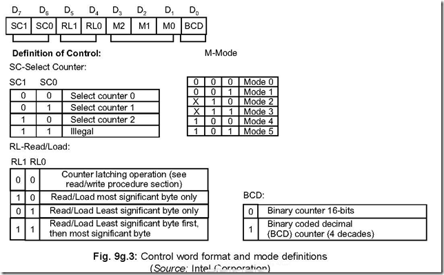
11. Write down the Control Word format as also the mode definitions.

Ans. The details of the control word format, as also the mode definitions are detailed below:

Programmable Interval Timer 8253 6-20-13 PM

The information stored in the control word gives the following details:

z Bits D7 and D6 (SC1 and SC0) select a counter.

z Bits D5 and D4 (RL1 and RL0) determine whether it is a Read or Load Count operation

and also whether it is Least Significant Byte or Most Significant Byte of the count that

is involved.

z Bits D3, D2, D1 (M2, M1, M0) determine the operating mode (i.e., Mode 0 to Mode 5)

z Bit D0 (BCD) determines the counting sequence in binary or BCD format.

12. How to ensure that a counter is loaded? Ans. For the above to be ensured, it is necessary that:

z The count value be written (a single byte or double byte—which depends on the mode selection by RL1 and RL0 bits).

z The above is then to be followed by a rising and a falling edge of the clock. Data, read before the falling edge of the clock, is an invalid one.

13. How writing operation is done in a counter (i.e., counter 0 or 1 or 2)? Ans. First the control word register is selected.

Secondly, the control word is to be appropriately chosen/written by

(a) selecting the counter in which writing is to be done (D7 – D6 bits).

(b) filling in D5 – D4 bits correctly (which takes care of 1 or 2 byte count).

(c) filling in D3 – D1 bits, which corresponds to Mode selection.

(d) filling in D0 bit—its content reflects the count down to be done in binary/BCD.

14. What will be the Control word register address if CS of 8253 is connected to

A7 via an inverter.

Ans. Since CS pin of 8253 is connected to A7 via an inverter, then A7 will have to be 1, i.e.,

A7 = 1. Again A1 and A0 will both have to be 1 to ensure writing in the control register. Assuming A6 to A2 to be 0, then the port address of the control word register will be

A7

A6

A5

A4

A3

A2

A1

A0

1

0

0

0

0

0

1

1

=

83H

15. Write the value of the control word if in a specific case counter 0 is to be selected in Mode 1. The counter should have a 16-bit count and that it should count down in binary. Lastly load the control word register with the control word value so formed. Assume address of control word register = 83H.

Ans. Control word for load operation is as follows:

Programmable Interval Timer 8253 6-20-57 PM

The program for loading the control word value 32H in the control register address 83H is as follows:

MVI A, 32H = Control word is loaded in accumulator

OUT 83H = The control word (= 32H) is written into the control word register, having address 83H.

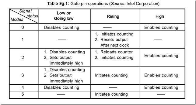
16. Show in a tabular form the conditions of the different Modes corresponding to the different status of the Gate signal.

Ans. This is shown below in a tabular form:

Programmable Interval Timer 8253 6-21-11 PM


17. Discuss the two methods of reading the value of the count in a counter while count is in progress.

Ans. There are two methods of doing the same

(a) Reading by halting/stopping the count

(b) Reading while counting is ‘ON’ (i.e., counting is in progress)

(a) Reading by halting: The procedure is as follows:

(i) The counter must be identified with appropriate A1 A0 status.

(ii) The counter is then halted by either disabling the Gate pin or inhibiting the

CLK input.

(iii) Then I/O read operation is done—the first I/O Read gets the LSB and the second

I/O Read gets the MSB.

(b) Reading while counting is in progress: For this to be effective, the mode register is loaded with a code that would load the present count (in a counter) to be latched on to a storage register.

The Mode Register Format for Latching Count is as follows:

Programmable Interval Timer 8253 6-21-29 PM

D5 – D4 are loaded with 0 each for latching the present counter content.

Then the Read command is invoked to the selected counter which gives the content

of the latched register—the counter must be programmed for two bytes and must be read

prior to any Write Command to the concerned counter.


Priority Interrupt Controller 8259

Priority Interrupt Controller 8259

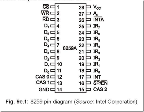
1. Draw the pin diagram of PIC 8259.

Ans. The following shows the pin details of PIC 8259.

Priority Interrupt Controller 8259 4-57-34 PM


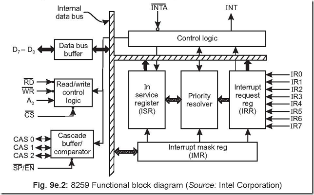
2. Draw the functional block diagram of PIC 8259.

Ans. The following shows the functional block diagram of 8259.

Priority Interrupt Controller 8259 4-58-03 PM

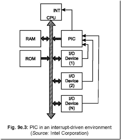
3. Draw the block schematic showing the interconnections between several I/O devices with PIC 8259, mP, RAM, ROM, etc.

Ans. The block schematic of the interconnections is shown below:

Priority Interrupt Controller 8259 4-58-30 PM

Fig. 9e.3: PIC in an interrupt-driven environment (Source: Intel Corporation)

4. How many interrupt levels can be handled by 8259? Ans. A single 8259 can handle up to 8 levels of interrupts.

Several 8259’s can be cascaded to handle up to 64 levels of interrupts.

5. In how many interrupt modes can 8259 operate and which command word is utilised for this?

Ans. 8259 can be operated in the following categories of interrupt modes:

(a) fully nested mode

(b) rotating priority mode

(c) special mask mode

(d) polled mode

Operation Command Word (OCW) is used for 8259 to be operated in the above mentioned modes.

6. How the 8259 is programmed?

Ans. 8259 is programmed by a set of Initialisation Command Words (ICWs). Each 8259 attached to the system must be initialised through ICWs. In all there are four ICWs (ICW1 to ICW4).

7. What are the jobs performed by ICWs? Ans. ICWs perform the following jobs:

z specifying the vectoring addresses for the individual interrupts.

z specifying single or cascaded mode of operation.

z level or edge triggering mode of operation.

8. What are the jobs performed by OCWs?

Ans. The operation command words (OCWs) are used to operate the PIC 8259 in various interrupt modes like fully nested mode, rotating priority mode, special mask mode and polled mode. The OCWs are also used for masking specific interrupts, status read operations, etc.

9. Describe how the PIC 8259 responds to interrupts?

Ans. PIC 8259 can accept a maximum of 8 interrupts from 8 different I/O devices, resolves the priority with regard to servicing the interrupts and issues an INT output signal, which

is connected to INTR input pin (pin 10 of 8085). 8085, in its turn, issues an INTA signal

via its pin 11, which is connected to INTA signal of 8259 (pin 26, an input pin for 8259).

In response, 8259 puts out a CALL instruction code on the data bus. This is read and

decoded by 8085, which then puts out two more INTAs. This is done by 8085 to read the

address where the Interrupt Service Subroutine (ISS) is written. Now the PIC 8259 puts out the address of this ISS on the data bus which is eventually read by 8085 and the program jumps to the ISS address as was previously programmed by 8259.

10. What are the different functional blocks in 8259? Ans. PIC 8259 has four different functional blocks viz.,

(i) Interrupt and Control logic block

(ii) Data bus buffer

(iii) Read/Write control logic block and

(iv) Cascade buffer/comparator section.

11. What the Interrupt and Control Logic Section consist of ?

Ans. This section consists of (a) Interrupt Request Register (IRR), (b) In Service Register (ISR), (c) Priority Resolver, (d) Interrupt Mask Register (IMR), (e) Control Logic Block.

12. Write down the sequence of operations for programming 8259.

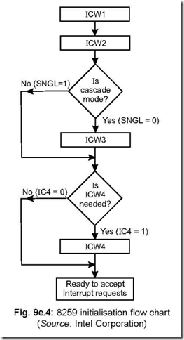
Ans. 8259 is programmed by issuing initialisation command words and operation command words. Initialisation command words are issued in a sequence. The following is the algorithm for initialising 8259.

1. Write ICW1.

2. Write ICW2.

3. If not in the cascade mode of operation, Go To Step 5.

4. Write ICW3.

5. IF ICW4 is not needed, then Go To Step 7.

6. Write ICW4.

7. Ready to accept interrupt sequence.

The flowchart for the above is shown in Fig. 9e.4.

Priority Interrupt Controller 8259 4-58-59 PM


13. Write down the main features of 8259. Ans. The main features of 8259 are as follows:

1. A single 8259 can handle 8 vectored priority interrupts.

2. 9 numbers of 8259 can be cascaded to have 64 levels of vectored priority interrupts in a mC system.

3. The priority modes can be changed or reconfigured dynamically at any time during the main program.

4. It can be operated in various interrupt modes—fully nested, rotating priority, special mask and polled.

5. 8259 can be used with either 8080/8085 or 8086/8088 microprocessor.

6. 8259 supports both edge and level triggered mode of interrupts.

7. The CALL address can be programmed to have a spacing of either 4 or 8 memory locations.

8. The data bus is buffered.

9. The AEOI (Automatic End Of Interrupt) can be programmed.

14. Write down the functions of IR0–IR7 pins.

Ans. There are 8 interrupt input lines from external devices with IR0 having the highest and IR7 the lowest priority. These interrupt requests are acknowledged by 8259 by (a) raising the corresponding IR input (i.e., any one of IR0 to IR7) from L to H and holding it high until acknowledged or (b) just by a high level.

15. What is the function of SP / EN pin?

Ans. This is slave program/enable buffer pin of 8259. It has dual functions:

(a) In the buffered mode it is used as an output to control the buffer transreceivers (EN).

It acts as an output pin to enable the data bus buffer of the system.

(b) In the non-buffered mode, it is used as an input pin to designate the 8259 to operate as a master (SP = 1) or slave (SP = 0).

The buffered or non-buffered mode of operation is determined at the time of initialisation of 8259 via ICW4.

16. Describe the functioning of the pins CAS0 – CAS2.

Ans. In a multiple 8259 structure, these three CAS lines form a private 8259 bus.

For a master 8259, these three pins act as output pins, but act as input pins for a slave 8259.

In a multiple 8259 structure, the master 8259 accepts interrupt requests from slave 8259. The master 8259 then generates a CALL opcode in response to the first INTA .

The slave 8259 provides the vectoring address. The master, via its three output pins (CAS0 – CAS2), gives out a code to identify the slave 8259. The slave 8259’s, connected to the system, each accepts this code from master 8259 and compare it with the code assigned to it during initialisation. The slave, so identified, then puts out the address of

the interrupt service subroutine on to DATA BUS during the second and third INTA

pulses from the CPU.

The identification of this master and slave 8259’s is done by the cascade buffer/ comparator block.

17. Discuss the vector data formats when 8085 is interrupted via INTR.

Ans. There are eight interrupt levels (IR0 – IR7) that generate CALL to eight equally spaced locations in the memory. These eight locations can be programmed to be spaced at an interval of either 4 or 8 memory locations.

The first interrupt vector byte released in response to the first INTA is shown in Fig. 9e.5. It is equivalent to the opcode for CALL instruction.

Priority Interrupt Controller 8259 4-59-20 PM

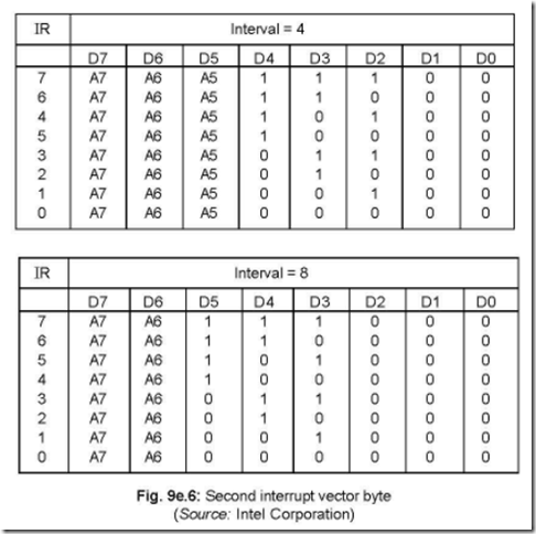
In response to the second INTA , the second interrupt vector byte released is shown in figure 9e.6. which shows interval spacings of either 4 or 8.

When the interval spacing is 4, 8259 inserts D0 – D4 bits automatically as per the levels of interrupts (i.e., IR0 – IR7), while D5 – D7 bits are specified during programming of 8259 through ICW1. Again for an interval of 8 between consecutive memory locations, D0 – D5 bits are inserted by 8259 automatically, while D6 – D7 bits are specified during programming of 8259 through ICW1.

Priority Interrupt Controller 8259 4-59-43 PM

The following figure shows the format of the byte released by 8259 in response to the third INTA .

Priority Interrupt Controller 8259 5-00-01 PM

This byte is completely programmable and is specified by ICW2.

18. Discuss the Initialisation Command Word 1 (ICW1).

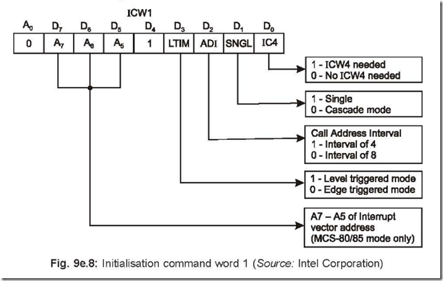
Ans. Whenever a Write Command is received with A0 = 0 and D4 = 1, it is interpreted by 8259 to be an initialisation command word ICW1. During ICW1, the following occur:

(i) The edge sense circuit is reset, which means that following initialisation, an interrupt request (IR) input must make a L to H transition to generate an interrupt.

(ii) The interrupt mask register (IMR) is cleared, i.e., all interrupts are now disabled.

(iii) IR7 input is assigned priority 7 (lowest).

(iv) The slave mode address is set to 7.

(v) The special mask mode is cleared and Status Read is set to IRR.

(vi) If D0 bit in ICW1 (IC4) is set to 0, then all functions selected in ICW4 are set to zero.clip_image018The format of the byte to be followed for ICW1 is shown below:

Priority Interrupt Controller 8259 5-00-24 PM

Bit D0 (IC4): It indicates whether ICW4 is needed or not. If it is ‘1’, then ICW4 is needed and if ‘0’, then ICW4 is not needed.

Bit D1 (SNGL): If this bit is ‘0’, then only one 8259 is in the system and if it is ‘1’ then additional 8259’s are there in the system.

Bit D2 (ADI): ADI stands for ‘address interval’. If this bit is ‘0’ then call address interval is 8 and if ‘1’ then call address interval becomes 4.

Bit D3 (LTIM): This bit determines recognition of the interrupts either in level triggered or edge triggered mode. If this bit = ‘0’, then it is edge triggered mode and if this bit is = ‘1’ then the input interrupts will be recognised if they are in the level triggered mode.

D5 – D7: These are A5 – A7 bits as shown under ICW1. For an interval spacing of 4, A0 – A4 bits are automatically inserted by 8259 while A0 – A5 are inserted automatically for an interval of 8. A5 – A7 bits are programmable as set by the bits D5 – D7 of ICW1.

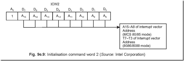
19. Discuss the Initialisation Command Word 2 (ICW2). Ans. The initialisation command word 2 i.e., ICW2 is shown below:

Priority Interrupt Controller 8259 5-00-44 PM

If A0 = 1 of the write command word is issued to 8259, following ICW1, it is interpreted as ICW2. ICW2 is used to load the high order byte of the interrupt vector address of all the interrupts. This byte is common for all the interrupts.

20. Discuss the Initialisation Command Word 3 (ICW3).

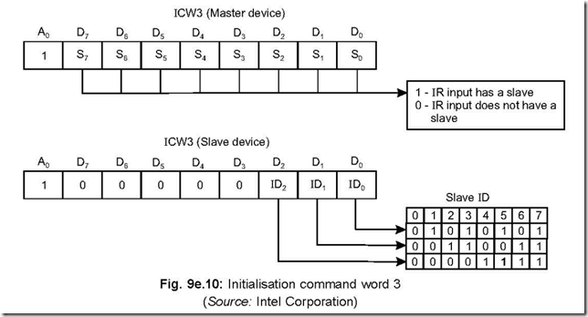
Ans. ICW3 can have two modes of operations: Master Mode ICW3 and Slave Mode ICW3. ICW3 is required only if several 8259’s are used in the mC system in a cascaded form.

The format of the byte (both for Master Mode ICW3 and Slave Mode ICW3) are shown

below:

Priority Interrupt Controller 8259 5-01-09 PM

Master Mode ICW3: For a 8259 to be treated as a master, we must have SP EN pin

= 1 in a non-buffered environment and M/S = 1 in ICW4 in a buffered environment.

Then each bit in ICW3 is used to indicate to the master whether it has a slave 8259

attached to it on its corresponding interrupt request (IR) input pin. A ‘1’ indicates the presence of a slave 8259 corresponding to that input and a ‘0’ indicates the absence of a slave.

If now a particular slave 8259 raises its INTR output, then the master generates a CALL instruction opcode and puts out the slave identification number on its output CAS0 – CAS2 lines. This number goes to the slave 8259’s via their CAS0 – CAS2 pins (these pins act as input pins for slave 8259’s). Thus the number is compared with the individual slave identification number loaded during initialisation. The slave which initially placed the INTR output is thus identified and hence it releases the vector address during the second and third INTA cycles.

Slave Mode ICW3: For a 8259 to be treated as a slave, we must have SP EN pin = 0 in

a non-buffered environment and M/S = 0 in a ICW4 in a buffered environment.

Bits D0 – D2 of ICW3 (in Slave Mode) assign the slave identification code (Slave ID). The slave ID is equivalent to the master IR input to which the INTR output of the slave is connected. The slave ID compares this number with its own CAS0 – CAS2 inputs so as to release the address vector.

21. Describe the Initialisation Command Word 4 (ICW4).

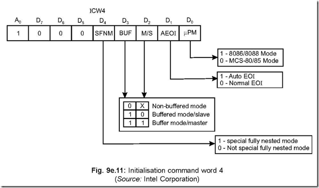
Ans. The format of ICW4 is shown below. ICW4 is loaded only if D0 bit of ICW1 (IC4) is set. As shown in Fig. 9e.11, ICW4 is loaded only if D0 bit of ICW1 (IC4) is set. The format of ICW4 is shown below.

Priority Interrupt Controller 8259 5-01-33 PM_thumb

The bit positions D0 to D4 are now explained:

mPM: This corresponds to D0 bit position and differentiates between 8086/8088 mode and MCS-80/85 mode.

AEOI: It stands for ‘automatic end of interrupt’. If AEOI bit (bit D1) = 1, then it is in auto EOI mode and if it is = 0, it is in normal EOI mode.

M/S: In the buffered mode, if M/S = 1, then 8259 is initialised as a master and if M/S = 0, then 8259 acts as a slave.

In the non-buffered mode, M/S pin has no significance. In this case, the characteristics of 8259 (i.e., whether 8259 is a master or a slave) is determined by SP EN pin.

BUF: This bit position (D3 bit) determines buffered/non-buffered mode of operation. If BUF = 1, then it is buffered mode of operation and the SP EN pin is used as an output to nable the data bus buffer of the system.

SFNM: This stands for Special Fully Nested Mode (bit D4). If SFNM = 1, then this mode is programmed.

22. Describe the Operation Command Words (OCWs).

Ans. There are three OCWs. These OCWs may be required to change the manner in which the interrupts are to be processed. For this to be achieved, the OCWs may be loaded any time after initialisation is over.

Priority Interrupt Controller 8259 5-02-01 PM_thumb

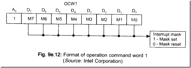
OCWl: It is used to enable/disable a particular interrupt request by programming the Interrupt Mask Register <IMR). IfM = 1, then the corresponding interrupt is masked and M = 0 indicates its unmasked condition.

A write command with Ao = 1is interpreted as OCWl, and written after ICW2.

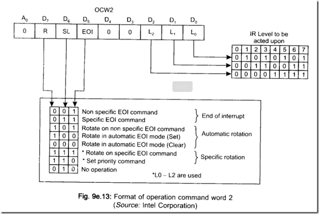
OCW2: The format for OCW2 is shown below:

Priority Interrupt Controller 8259 5-02-39 PM_thumb

A write command with A0 = 0 and D4 D3 = 00 is interpreted as OCW2. ‘R’ and ‘SL’ stand for Rotate and Select Level respectively. The bits corresponding to R, SL and EOI control the Rotate and End of Interrupt modes. Bits L2 – L0 "specify the interrupt level which is to be acted upon when SL is in active condition.

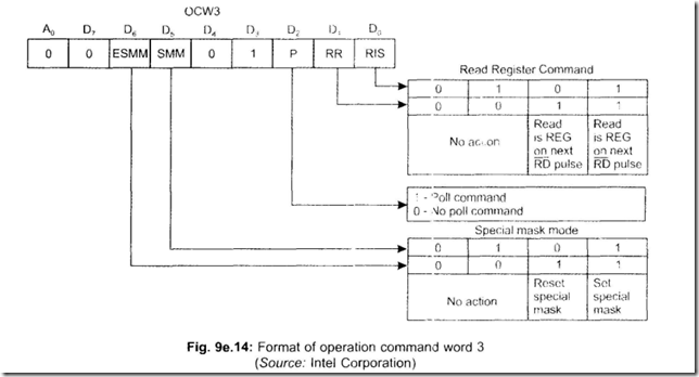
OCW3: The jobs performed by OCW3 are as follows:

(a) to read the status of registers.

Priority Interrupt Controller 8259 5-03-02 PM_thumb

23. Describe the F (Fully Nested Mode).

Ans. This mode is auto-set after initialisation is over-i.e., it is a default mode. Th.s mode can only be changed through Operation Command Words ( OCW s ).

IRO is assigned the highest priority ( pnority 0) and IR7 the lowest priority (priority 7). When 8259 acknowledges an interrupt request via its INTR pin, it finds out the highest priority and the corresponding bit in the In Service Register (ISRl is set. The resetting of this bit in ISR can occur in one of the following ways:

(a) When the CPU issues an EOI (End oflnterruptl through OCW before coming out of ISR.

(b) If AEOI (Automatic End of Request) mode is set in ICW4 during initialisation, the corresponding ISR bit is automatically reset-it occurs on the trailing edge of the last

(third) INTA pulse.

When a particular ISR bit is set. (a) all lower level interrupts and (bl same level interrupts remain in the inhibited condition.

But a higher level interrupt will force the 8259 to generate an INTR, but the same will be acknowledged if the Interrupt Enable F!F has already been enabled via software while the interrupt service subroutine is in progress.

24. Describe the EOI command.

Ans. This command stands for End of Interrupt ( EOI l.

The interrupt service bit (that is being currently serviced l can be reset by an End of Interrupt Command. This is issued by the CPU, usually just befiwe coming out of the interrupt service routine.

There are two ways in which the EOI can be exerted—in the Fully Nested Mode (FNM) and non FNM.

In the FNM, a non-specific EOI command is issued by the CPU. This is an OUT instruction by the CPU to 8259. This is derived by A0 = 0, D7 D6 D5 D4 D3 = 00100 with D2 D1 D0 can have any value. This is apparent from the format of the operation command word 2 i.e., OCW2. This OUT instruction is issued by CPU before exiting from the interrupt service subroutine. On receiving this instruction, 8259 resets the highest level of interrupt (i.e., the current one that which is being serviced).

In non FNM, 8259 cannot determine the last interrupt acknowledged. Thus in this case, the CPU will have to issue a specific EOI command signalling out the specific interrupt service bit that is to be resetted. This is done under OCW2 with A0 = 0, D7 D6 D5 D4 D3 = 01100 and D2 – D0 specifies the level on which the EOI command is to act.

25. In the cascade mode, how many EOI commands are to be issued?

Ans. In such a case, two EOI commands must be issued—one for the master and one for the slave.

26. Describe the AEOI command.

Ans. This mode can only be used for a master 8259 and is set by ICW4. 8259 performs a non specific EOI on the trailing edge of the third (i.e., last) INTA pulse.

27. Explain Special Fully Nested Mode (SFNM).

Ans. In the cascaded mode of operation, if a slave receives a higher priority interrupt request than one which is in service (through the same slave), it would not be recognised by the master. This is because the master ISR bit is already in the set condition, thereby it ignores all requests of equal or lower priority. The higher priority interrupt won’t be serviced until after the master ISR bit is reset by an EOI command. This is most likely to happen after the completion of the lower priority routine.

This is where the SFNM comes into. It is meant only for the master and done during master initialisation (through ICW4). In this mode, the master will ignore interrupt requests of lower priority, but responds to requests of equal or higher priority.

The following are the differences between FNM and SFNM:

(a) In SFNM, the slave is allowed to place an interrupt request (of higher priority than the one currently being serviced). The master recognises this higher level interrupt, which in its turn places this interrupt request to the CPU.

(b) In SFNM, the software must determine if any other slave interrupts are pending before issuing an EOI command to the slave and then reading its ISR (In Service Register). If the ISR contains all zeroes, then no interrupt from the slave is in service and an EOI command can be sent to the master. If the ISR is not all zeros, an EOI command should not be sent to the master. Clearing the master ISR bit with an EOI command while there are still slave interrupts in service would allow lower priority interrupt to be recognised by the master.

28. Mention the types of Rotating Priority Mode of interrupt.

Ans. The Rotating Priority Mode can be set in

(a) Automatic Rotation

(b) Specific Rotation.

Priority Interrupt Controller 8259 129

29. Discuss the Automatic Rotation.

Ans. In situations where several communicating channels are connected to 11C system, all the channels should be accorded equal priority in sharing information with the IJC.

Thus when a peripheral is serviced, all other equal priority peripherals should be

given a chance to be serviced before the original peripheral is serviced a second time around. This is accomplished by automatically assigning a peripheral the lowest priority after being serviced. Thus a device, presently being serviced, would have to wait until all other devices are serviced.

Automatic rotation is of two types:

(a) Rotate on non-specific EOI Command.

(b) Rotate on automatic EOI Mode.

Rotate on non-specific EOI Command: When the rotate on NSEOI command is issued, the highest ISR bit is reset and the corresponding IR level is assigned the lowest priority.

Let IRO has the highest and IR7 the lowest priority. Let also that IR6 and IR4 are in service with IR4 accorded the highest priority. Bit 4 in the ISR is reset when a NSEOI command is executed. Mter this, IR4 besomes the lowest priority and IR5 becomes the highest priority. The situations are explained in the following figure with the left side indicating the situation before the command is execut.ed and the right side after the command execution.

Priority Interrupt Controller 8259 5-03-27 PM_thumb

Rotate in Automatic EOI Mode: This mode works much like the rotate on NSEOI command. The main difference between the two lies in the priority routine done

automatically after the last INTA pulse of an interrupt request. To enter or exit from this mode, a rotate-in-automatic EOI Set Command and rotate-in-automatic EOI Clear Command is provided.

30. Explain Specific Rotation.

Ans. In this mode, the lowest priority can be assigned to any of the IR levels (between 0 and 7) as specified by OCW2.

This mode is set by CPU by issuing an OUT instruction in the following manner:

A0= 0

D7 D6 D5 D4 D3 = 1 10 0 0

D2 D1 D0 bits specify which interrupt level is to be accorded lowest priority. This mode is independent of EOI command.

31. Describe Special Mask Mode.

Ans. The special mask mode enables interrupts from all levels except the level presently in service. This is done by masking the level that is in service and then issuing the special mask mode command. Once the special mask mode is set, it remains in effect until reset.

The Special Mask Mode can be set by making ESSM and SMM bits ‘1’ in OCW3. When a mask bit is set in OCW1, all further interrupts at that level are inhibited, while interrupts on all other levels that have not been masked by OCW1 (both lower and higher) are enabled. Thus it is possible to selectively enable interrupts by programming the mask register.

The special mask mode is cleared by loading OCW3 as follows:

ESSM = 1

and SMM = 0

32. Describe the Polled Mode interrupt scheme.

Ans. In this mode, the interrupting devices seeking services from 8085 are polled one after another to detect which device has sought for interrupt request. The INT output of 8259 is either not connected to INTR input of 8085 or the interrupts are disabled by software means.

Bit D2 (i.e., P) in OCW3 is set to ‘1’ in the Polled mode. 8259 is then read by masking its RD and CS pins ‘0’. The ISR bit is set corresponding to the highest level interrupt

in the IRR. A byte is put out on the data bus as shown below:

Priority Interrupt Controller 8259 5-03-46 PM_thumb

If D7 = 1, then it implies that an interrupt needs servicing, while D2 – D0 bits (i.e., W2 – W0) correspond to the highest priority interrupt level which is requesting service.

Since INTR line is not in use in the polled mode, hence more than one 8259 may be connected in the master mode. Hence it is possible to have more than sixty four levels of interrupts in this mode.

33. On which registers status read operations can be done?

Ans. Status read operations can be done on Interrupt Request Register (IRR), In-Service Register (ISR) and Interrupt Mask Register (IMR).

34. How IRR status read operation is done?

Ans. A particular 8259 can be set up for an Interrupt Request Register (IRR) read operation by inserting in OCW3 RR (read register) = 1 and RIS (Read ISR) = 0. Following this, RD

= 0 and CS = 0 are made on the 8259, which thereby puts out the contents of IRR on the data bus.

In the non-polled mode of 8259, A0 should be made ‘0’ so as to put out the contents of IRR status word after the IRR has been set for status read operation.

35. Discuss the ISR status read operation.

Ans. A particular 8259 can be set up for an In-Service Register (ISR) read operation by inserting in OCW3 RR = 1 and RIS = 1. Following this RD = 0 and CS = 0 are made on the 8259,

Priority Interrupt Controller 8259 131

which thereby puts out the contents of ISR on the data bus.

In the non-polled mode of 8259, A0 should be made ‘0’ so as to put out the contents of ISR status word after the ISR has been set for status read operation.

36. How IMR status read operation is done?

Ans. An Interrupt Mask Register (IMR) status read operation on a 8259 is done with A0 = 1, RD = 0, CS = 0. This causes the contents of IMR to be put out on the data bus. For an IMR status read operation, OCW3 is not needed.

37. Which status read operation is performed by default after initialisation of 8259?

Ans. The default status read operation is the IRR status read, after the initialisation of 8259.

38. Mention when status read operation is not possible.

Ans. When OCW3 is set in the polled mode with P = 1 and RR = 1, status read operation is not possible.

39. Discuss the Default IR7 routine.

Ans. An interrupt via the INTR input will be treated as a valid interrupt if it remains high until after the falling edge of the first INTA pulse. Then a valid IR7 input occurs

resulting in a normal CALL to the IR7 routine. If it is otherwise, a default CALL to the IR7 routine will be generated.

A normal IR7 operation sets the ISR bit while a default IR7 operation does not do so. For this IR7 is normally used for RET instructions. If IR7 is to be utilised for other purposes, then the default IR7 operation is first to be checked. This is done by a status read operation of ISR at the beginning of interrupt service routine for IR7. If after this read operation, IR7 input = 1, then it is a valid interrupt, otherwise not.

40. Distinguish between NSEOI, SEOI and AEOI.

Ans. These three stand for non-specific end of interrupt, specific end of interrupt and automatic end of interrupt.

An NSEOI command sent from the mP lets the 8259 know when a service routine has been completed, but without any specification of its exact interrupt level. The 8259 determines the interrupt level (the highest priority interrupt in service) and resets the correct bit in the ISR.

The NSEOI is best suited when servicing is always at the highest priority level. When 8259 receives a NSEOI command, it simply resets the highest priority ISR bit.

The main advantage of this mode is that it is not necessary to specify the IR level. NSEOI command is not suited for the following two cases:

(a) Using a set priority command within an interrupt service routine.

(b) Using a Special Mask Mode.

A SEOI command sent from mP to 8259 lets it know when a service routine of a particular interrupt level is completed. A SEOI command resets a specific (particular) ISR bit—thus any one of the eight IR levels can be specified.

A SEOI command is needed when 8259 is unable to determine the IR level.

A SEOI command is best suited for situations in which priorities of the interrupt

levels are changed during an interrupt routine (Specific Rotation).

The AEOI mode scores over the EOI modes in that no command has to be issued in

AEOI mode. Thus AEOI mode greatly simplifies programming and lowers code requirements within interrupt routines.

AEOI mode should be used continuously because the ISR bit of a routine presently in service is reset right after its acknowledgement. It thus leaves behind nothing in the ISR about which particular bit is being serviced. If any interrupt request occurs during this time, it will be serviced (provided all interrupts are enabled) regardless of its priority—whether low or high.

Another peculiar problem—called ‘over nesting’ may happen in this case. It occurs when an IR input keeps as interrupting its own routine. It results in unnecessary stack pushes which could fill up the entire stack in a worst case situation.

41. Describe how several PICs are cascaded together.

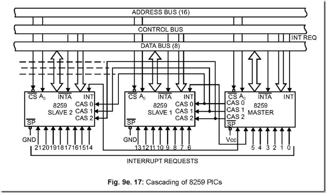
Ans. Several PICs can be cascaded together—in all 9-with one PIC acting as the master and the rest eight as slaves and shown in Fig. 9e.17. SP pin of the master is connected to Vcc, whereas for slave PICs, their SP pins are connected to ground. The INT outputs of the slave PICs are connected to one of IR0-IR7 pins of the master. The registers within the PICs are allocated separate addresses by using separate CS signals. Initialisation of each of the PICs are done separately.

Priority Interrupt Controller 8259 5-04-23 PM_thumb

When an interrupt comes, it activates one of the IR input lines of a slave PIC and this in turn activates one of the IR lines of the master (via the INT output pin of the slave PIC which has been interrupted). This in turn interrupts the CPU. The INTA output from the master enables the corresponding CAS0-CAS2 lines of the slave PIC— this releases the vector address of the data bus in the second and third INTA cycles.


8254: Programmable Interval Timer

8254: Programmable Interval Timer

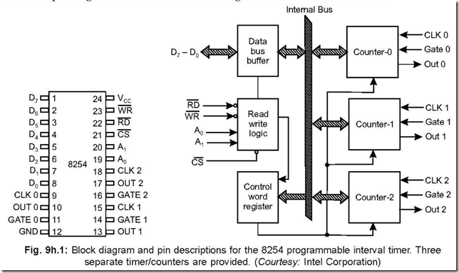
1. Draw the pin diagram and functional block diagram of 8254.

Ans. The pin diagram and functional block diagram of 8254 are shown below:

8254 Programmable Interval Timer 6-30-20 PM

2. How many counters are there in 8254?

Ans. There are three 16-bit counter registers, each of which can be programmed as a timer or an event counter. The counters are named as COUNTER 0, COUNTER 1 and COUNTER 2.

3. How programming is done in 8254?

Ans. The programming is done by writing a control word in the Control Word Register.

4. In how many modes can 8254 operate?

Ans. 8254 can operate in six possible operating Modes—Mode 0 to Mode 5.

5. What kind of outputs are available from the different operating modes.

Ans. From the six different operating modes, the outputs which are available are: event counter, one-shot, square-wave generator, divide-by-N counter, hardware triggered strobe and software triggered strobe.

6. What happens when the Terminal Count (TC) of a counter is reached?

Ans. The counters operate in count down mode. When a counter counts down to zero, it is called ‘Terminal Count’. When TC for a particular counter occurs, the following may occur:

z an interrupt can be requested

z a one-shot pulse can be terminated

z a strobe pulse can be generated

z the logic level of a square wave can be toggled.

7. What are the differences between timers 8253 and 8254?

Ans. Timer 8254 is actually a “Superset” of timer 8253 and is pin compatible with the latter.

There are two differences between the two, which are

z 8254 has read back mode facility—which means that the status of a particular mode can be read after programming. This facility is not available with 8253.

z The maximum clock frequency of 8254 is 10 MHz, whereas that of 8253 is 2 MHz.

8. In how many forms can the control word register be used?

Ans. The control word can be used in three formats—Standard mode, counter latch mode and Read back mode.

9. How one of the Six Modes (Mode 0 to Mode 5) is selected?

Ans. The particular mode is selected by the standard form of the control word in the control word register.

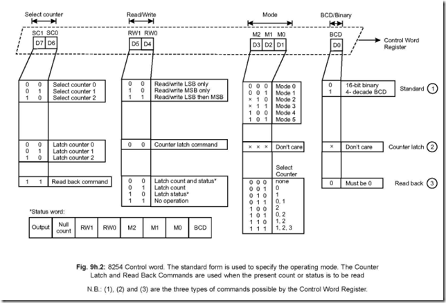
10. Draw the control word register format and discuss.

Ans. The control word of the control word register is shown Fig. 9h.2.

The control word byte is divided into four parts D7 – D6, D5 – D4, D3 – D2 – D1 and D0. The different combinations of these eight bits give rise to ‘standard’ mode, ‘Counter latch’ mode or ‘Read back’ mode and are self evident from the figure.

11. Discuss the six different modes in which 8254 can operate.

Ans. The six different modes are Mode 0 to Mode 5. These are discussed below:

Mode 0: This is an ‘event counter’, when GATE = 1, the counter will start decrementing from its stored value on the falling edge of the second pulse of CLK input. OUT will go high when ‘terminal count’ is reached. This OUT signal can be utilised as an interrupt input to the microprocessor.

Mode 1: It is ‘hardware triggered one shot’, when the rising edge of the GATE pulse is received, OUT goes low and remains low till TC (terminal count) is reached. Then OUT goes high. This low one shot duration is equal to the stored value in the counter multiplied by the CLK period.

Mode 2: It is a ‘Divide-by-N’ counter, when GATE = 1, OUT goes low for one period of the CLK input after the stored count is decremented to 1. The initial (or stored) count will then automatically get reloaded and the cycle repeats.

Mode 3: It is a ‘square wave generator’. It is identical to Mode 2, but the duty cycle (= on time/period) here is 50%. In case, the initial count is an odd number, OUT then will be high for one more clock cycle then it is low.

8254 Programmable Interval Timer 6-31-06 PM

Mode 4: It is a ‘software triggered mode’. If GATE = 1, OUT goes low for one period of the CLK input N clock cycles after, where N is the initial (or stored) number in the counter. For second strobing to be done, N must be reloaded in the counter.

Mode 5: It is a ‘Hardware triggered mode’. On the appearance of rising edge of the GATE input, the stored or initial count starts decrementing to 0. When TC occurs, OUT goes low for one period of the CLK input.

12.

A1

A0

0

0

Write into Counter 0

0

1

Write into Counter 1

1

0

Write into Counter 2

1

1

Write Counter word

How the three counters and the control word are selected? Ans. The combination of A1 A0 select the above and shown below:

13. Write down the port addresses of the three counters and the control word

ææ

register. The CS signal is derived on the basis of A7 – A4 = 1111 and A3 – A2 =

00.

Ans. The port addresses of the counters and the control word register are determined as follows:

A7

A6

A5

A4

A3

A2

A1

A0

Port address of

1

1

1

1

0

0

0

0

=

F0

—>

Counter 0

1

1

1

1

0

0

0

1

=

F1

—>

Counter 1

1

1

1

1

0

0

1

0

=

F2

—>

Counter 2

1

1

1

1

0

0

1

1

=

F3

—>

Control Word Register.

14. Write down the Control Word so that Counter 1 operates in Mode 0 in binary

sequence.

Ans. By having a look at the control word register, the control word will be as follows: 0 1 1 1 0 0 0 0 = 0111 0000 = 70

While writing the above control word, it is assumed that Counter 1 is to be loaded with a 2-byte count.


8155/8156: Programmable I/O Ports and Timer

8155/8156: Programmable I/O Ports and Timer

1. In what way 8155 and 8156 differs?

Ans. The Chip Enable (CE) signal is active low for 8155, whereas it is active high for 8156.

2.What are the essential features of 8155.

Ans. The essential features of 8155 are

*8-bit 256 word RAM memory

*Two programmable 8-bit I/O port

* One programmable 6-bit IO port

*One programmable 14-bit binary Timer/Counter

* An internal address latch

*A control/status (C/S) register

* An internal decoder.

3. Functionally, how many sections are there in 8155?

Ans. Functionally, it has two sections—(a) a R/W memory and (b) programmable I/O and timer section.

4. Is it necessary to demultiplex the lower order bus AD7 –AD0 externally for 8155 to be connected to 8055?

Ans. No, it is not. This is because ALE, IO/ M , RD and WR signals of 8085 can be connected directly with 8155.

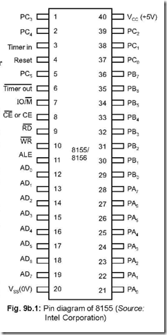
5. Draw the pin diagram of 8155.

Ans. The pin diagram of 8155 is shown in Fig. 9b.1.

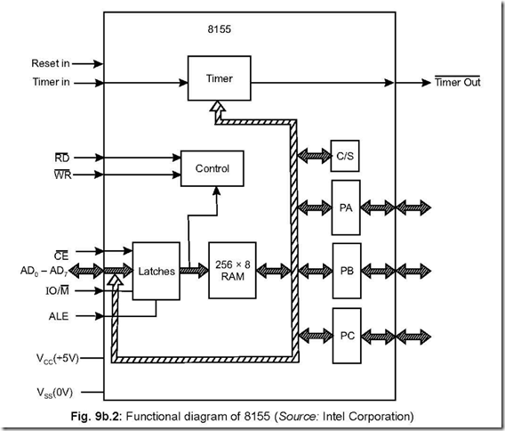
6. Draw the functional block diagram of 8155.

Ans. The functional block diagram of 8155 is shown in Fig. 9b.2 :


8255 Programmable Peripheral Interface 8-00-57 PM

8155-8156 Programmable I-O Ports and Timer 8-48-52 PM

7. How the different ports, control/status register, timers are accessed? Write their addresses also.

Ans. The different combinations on the address lines A2, A1, A0 select one of the above, as shown:

A2

0

A1

0

A0

0

==>>

Control/Status Register

0

0

1

===>>

Port A

0

1

0

===>>

Port B

0

1

1

===>>

Port C

1

0

0

===>>

LSB Timer

1

0

1

===>>

MSB Timer

The other five (viz., A7 to A3) on the address lines are as: 0 0 1 0 0. Thus

A7 0

A6 0

A5 1

A4 0

A3 0

A2 0

A1 0

A0 0

===>>

Address

20H

Register/Port/Timer

Control/Status register

0

0

1

0

0

0

0

1

===>>

21H

Port A

0

0

1

0

0

0

1

0

===>>

22H

Port B

0

0

1

0

0

0

1

1

===>>

23H

Port C

0

0

1

0

0

1

0

0

===>>

24H

LSB timer

0

0

1

0

0

1

0

1

===>>

25H

MSB timer

It is to be noted that the control/status register is having the same address 20H, but

the control register is accessed with WR = 0 and RD = 1. For status register access, WR

= 1 and RD = 0. The control register can never be read. For any future reference, the

control register content is stored in some accessible memory location.

8. Draw the control word format and discuss the same in detail.

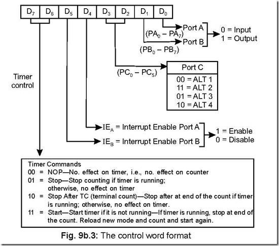
Ans. The control word loaded in the control register configures the different ports and the timer of 8155. The control word format is shown below:

8155-8156 Programmable I-O Ports and Timer 8-49-42 PM

The control register contains eight latches. The content of the lower 2 bits, viz., D1 – D0 configure ports A and B as input/output. Bits D3 and D2 configure bits PC0 – PC5 of port C (Port C is a 6-bit port while ports A and B both are of 8-bits) and can have four combinations—ALT1, ALT2, ALT3, ALT4 depending on the combinations of D3 and D2. Bits D5 and D4 are enable/disable pins for ports A and B respectively which enable/ disable the internal flip-flop of 8155. Bits D7 and D6 contain the timer commands.

As already mentioned, combinations of D3 – D2 bits give rise to ALT1 to ALT4 modes, which assigns port C bits in different configurations and shown below:

Table 9b.1: Port C pin assignment (Source: Intel Corporation)

Pin

ALT1

ALT2

ALT3

ALT4

PC0

PC1

PC2

PC3

PC4

PC5

Input Port

Input Port

Input Port

Input Port

Input Port

Input Port

Output Port

Output Port

Output Port

Output Port

Output Port

Output Port

A INTR (Port AInterrupt)

A BF (Port A Buffer Full)

A STB(Port A Strobe)

Output Port

Output Port

Output Port

A INTR (Port A Interrupt)

A BF (Port A Buffer Full)

A STB(Port A Strobe)

B INTR (Port B Interrupt)

B BF (Port Buffer Full)

B STB(Port B Strobe)

ALT1 and ALT2 correspond to simple input/output of Port C respectively. In ALT3 mode, PC0 – PC2 bits are used as control signals for port A, while pins PC3 – PC5 act as output pins. In ALT4 mode, PC0 – PC2 bits are used as control signals for port A, while PC3 – PC5 bits are used as control signals for port B.

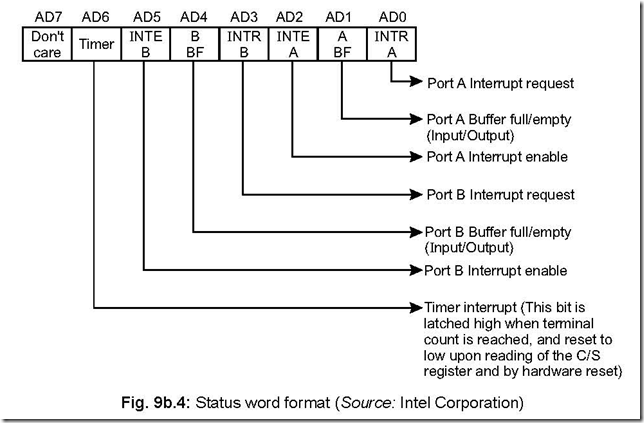
9. Draw the status word format and discuss the same. Ans. The status word format of 8155 is given below:

8155-8156 Programmable I-O Ports and Timer 8-50-37 PM


It has seven latches. Bit D7 is the ‘don’t care’ bit. Bit D6 contains the status of the timer. Bits D5 – D3 pertain to status of port B while bits D2 – D0 to that of Port A.

10. Discuss the timer section of 8155 and discuss its operating modes.

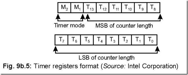
Ans. The timer section consists of two 8-bit registers. 14-bits of the two registers comprise to specify the count of the timer, which counts in a count-down manner. Contents of bits 6 and 7 of the most significant byte of the register decide the mode of operation of the counter. The following shows the timer register format. The timer section needs a ‘TIMER IN’ pulse, which is fed via pin 3 of 8155. A square wave or a pulse

is obtained via pin 6 (TIMER OUT) when the terminal count (TC) is reached. The maximum and minimum values of the count down timer are 3FFH and 002H respectively. A single square wave or a continuous square wave or a single pulse

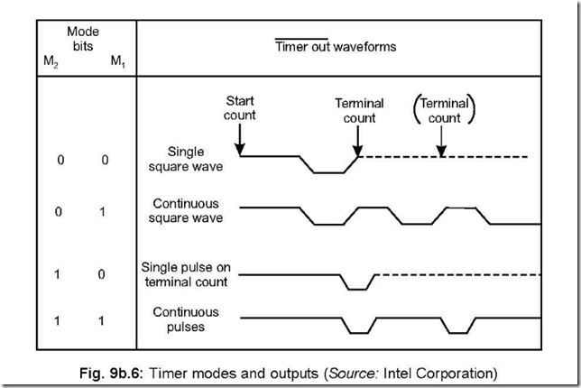
on TC or a pulse on each TC (i.e., continuous pulses) are obtained, depending on the mode setting bits M2 and M1.

The following figure shows the nature of the outputs for the different modes.

8155-8156 Programmable I-O Ports and Timer 8-51-03 PM


8155-8156 Programmable I-O Ports and Timer 8-51-31 PM

11. What happens when a high is applied on RESET ?

Ans. A high reset input resets the counter. To restart counting after resetting, a START command is required through the control register.


8279: Programmable Keyboard/Display Interface

8279: Programmable Keyboard/Display Interface

1. Draw the pin diagram of 8279.

Ans. The pin diagram of 8279 is shown below:

8279  Programmable Keyboard-Display Interface 4-41-21 PM

Fig. 9d.1: 8279 pin diagram (Source: Intel Corporation)

2. Draw the functional block diagram of 8279 and elaborate on the different blocks. Ans. The functional block diagram of 8279 is shown below:

The different functional blocks of 8279 are (a) a CPU interface, (b) a set of scan lines,

(c) input lines for key data and (d) output lines for display data.

The CPU interface consists of 8-bit data bus along with CS , RD , WR , CLK, RESET

and IRQ lines. IRQ is an output line which becomes 1 (active) when key data exists in an internal RAM of 8279. This line is normally connected to one of the hardware interrupt

8279  Programmable Keyboard-Display Interface 4-41-57 PM

Fig. 9d.2: Functional block diagram of 8279 (Source: Intel Corporation)

lines of the CPU. A high on A0 indicates that the signals in/out pertain to command/ status while a low on A0 indicate that they are data.

The scan lines (SL0–3) along with the eight return lines (RL0–7) can be used for construction of a keyboard matrix. SHIFT and CNTL/STB signals (both inputs) contribute the characteristics for individual keys.

The display output is available through A0–3 and B0–3 which can be used together as

an 8-bit port. BD (output signal) is used for display blanking purposes.

3. What are the two most important functions performed by 8279? Ans. The two most important functions performed by 8279 are as follows:

(a) It scans the keyboard, then detects the key press and transmits to the CPU information which corresponds to the particular key pressed.

(b) It puts out data received from the CPU, for use by the display devices.

4. What are the various input modes in which 8279 operate? Ans. There are three input modes in which 8279 operates:

z Scanned Keyboard Mode

z Scanned Sensor Matrix Mode

z Strobed Input Mode.

5. How many character definitions are possible using 8279? Ans. A maximum of 256 character definitions are possible using 8279.

6. When the CPU is actually involved for the scan and display functions to be realised?

Ans. For the above two functions to be realised, CPU involvement is required only when data is actually transmitted to or received from the CPU.

7. What are the modes in which the four scan lines can operate?

Ans. The four scan lines (SL0 – SL3) can be operated in two modes—encoded and decoded mode.

8. Discuss the encoded and decoded mode.

Ans. Encoded mode: Here 16 lines are generated using the 4 scan lines and a 4 to 16 external decoder, although the manufacturers recommend not to use the SL3 line. Thus eight decoded scan lines are possible with SL0 – SL2 lines and a 3 to 8 decoder. These 8 lines, along with eight return lines (RL0 – RL7) can form a 8 × 8 keyboard matrix. Thus it leads to 64 different character definitions. With SHIFT and CONTROL input lines taken as two additional input lines, total character definitions possible = 64 × 22 = 256.

Decoded mode: Using the internal decoder present in 8279, SL0–SL3 lines are decoded. With SHIFT and CONTROL lines along with RL0 – RL7 lines, total character definition possible here is = 4 × 8 × 4 = 128.

9. Describe the Scanned Keyboard Mode.

Ans. Both encoded and decoded scan versions are applicable in this case. This mode can be divided into two ways.

z 2 key lockout

z N-key rollover

In this mode, the pressing of a key generates a unique 6-bit data (called ‘position data’) which is characteristic of the position of the key pressed. These 6-bits, along with CNTL and SHIFT form a 8-bit word, shown below. Of the position data D5 – D0, Scan bits correspond to D5 – D3 and Return bits correspond to D2 – D0. D5 – D3 bits correspond to the position of the row on which the key is pressed while D2 – D0 correspond to the position of the column on which the key is pressed. This 8-bit word gets stored in the RAM of 8279 (in FIFO order) and consequently the IRQ (interrupt request, an output line) line goes high. This IRQ line is connected to one of the hardware interrupt pins of the CPU. On recognition of the interrupt input by the CPU, the RAM in 8279 is read in FIFO form. Once this reading by CPU is over IRQ line of 8279 goes low but will become high if the RAM contains another data.

8279  Programmable Keyboard-Display Interface 4-42-28 PM

2 Key Lockout: In this 2 key lock out version of Scanned Keyboard Mode, when any key is pressed, it waits for next two scans to check whether any other key is pressed or not. Several possibilities do arise which need to be addressed separately.

(a) No other key press is detected. Then data corresponding to key press is taken to RAM in 8279 and IRQ output line goes into high state.

In case this internal RAM (of 8279) is already full, the keyed data is ignored and the error flag is set (= 1).

(b) If one or more additional key pressing occurs, no data entry into RAM is allowed. In this case two possibilities occur:

(i) If the first key (i.e., the key which was pressed first) is released ahead of others, then the key press is ignored.

(ii) If all the keys are released before the key first pressed, then data corresponding to first key pressed, is entered into RAM of 8279.

Another possibility is pressing of two keys within one debounce cycle (the time required for eliminating contact bounce effect is known as contact debounce time). In this case, no key is recognised. When one key is released, the other key that remains pressed is recognised as a single valid key depression.

N-Key Rollover: In this case, the debounce circuit waits for two scans after the first key press. It then checks whether key is still in the pressed condition or not. If the answer is yes, then the data corresponding to the key press is taken into RAM of 8279. No limit is there to the number of key presses. For simultaneous key presses, data are entered according to the order of key press.

If within a single debounce cycle, two keys are found pressed, the error flag is set

and data entry into the RAM is prohibited. The error flag can be read from the FIFO STATUS word and can be cleared by a CLEAR command (CF = 1).

10. Describe the Scanned Sensor Matrix Mode.

Ans. In the Scanned Sensor Matrix Mode of operation, the keys are arranged in the form of a matrix, with the scan lines (SL0 – SL2) forming the columns and return lines (RL0 – RL7) forming the rows. The open/closed condition of the key is stored in a RAM location. The size of the matrix be 8 × 8 or 4 × 8 for encoded and decoded scan lines respectively.

The data entering via the RL lines are admitted into eight columns of the sensor RAM—thus each RAM position corresponds to a specific switch position. Apart from switches, other logic circuit output lines can be connected to the RL lines.

11. Describe the Strobed Input Mode.

Ans. In this mode, data are placed on the return lines (RLs). The source of data may be an encoded keyboard or a switch matrix. The data so entering go to FIFO RAM and are accepted on the rising edge of a CNTL/STB pulse.

12. State the options available in the display mode. Ans. The available options are:

z Display format—either left entry (also known as typewriter mode), or right entry (also

known as calculator mode).

z Number of display characters: eight or sixteen.

z Organisation of characters—Single 8-bit or dual 4-bit type.

13. Discuss the Left Entry (Typewriter) Mode of Display format.

Ans. In the left entry (or typewriter) mode, the first entry goes to address 0, the second entry to address 1 and so on. The first entry goes to the left most display position. The second entry to the just right of the earlier one. Thus the 16th entry goes to 15th address position. It is to be remembered that the 17th entry goes to the RAM address 0 again, 18th entry goes to RAM address 1 etc, and is shown in Fig. 9d.4.

8279  Programmable Keyboard-Display Interface 4-42-48 PM

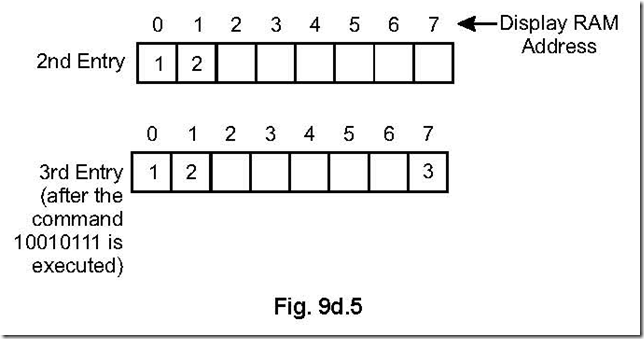
In this mode, data can be entered at any arbitrary RAM address position. Assuming a 8-position display, if a command 10010111 is inserted after the 2nd entry, then the next data will be displayed at 7th position. The explanation is like this: The most significant three bits 100 represent the code for WRITE display, the next bit, i.e., 1 is for auto-increment and the right most four bits i.e., 0111(= 7) represent the position at which the next data will be filled in. This is shown in Fig. 9d.5.

8279  Programmable Keyboard-Display Interface 4-43-17 PM

14. Discuss the Right Entry (Calculator) Mode of Display format.

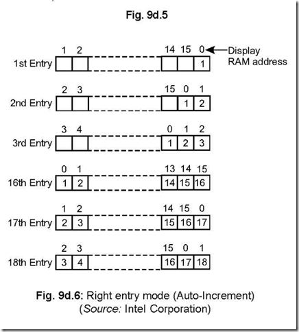
Ans. In the right entry (calculator) mode, the characters are entered from the right most position. As characters are entered one after another, the present data occupies the right most position, just the earlier one occupies the left of the right most position etc. This is explained in Fig. 9d.6.

8279  Programmable Keyboard-Display Interface 4-43-32 PM

In this mode, no correspondence exists between RAM address and the display position.


15. What are the different types of software operations possible with 8279. Ans. The following software operations are possible with 8279:

z Keyboard/display mode set

z Program clock

z Read FIFO/Sensor RAM

z Read Display RAM

z Write Display RAM

z Display Write Inhibit/Blanking

z Clear

z End Interrupt/Error Mode Set

z Status Word.

16. In how many ways data can be entered into a microprocessor?

Ans. There are three different ways of entering data into microprocessor—these are

z reading data from a DIP (on/off) switch.

z reading data from push-button keys.

z keys arranged in matrix form and read by software technique.

17. What is meant by contact bounce? How it is eliminated?

Ans. When an electromechanical switch is switched over from an off to on condition, the contact does not become firm on the first count. It loses contact and then makes it—this process repeats itself for a number of times before the contact is firmly placed. This occurs for a very small duration of time.

This thus leads to erroneous operation in digital circuits. This problem can be eliminated by a hardware circuit—called ‘contact debouncers’ or by software technique (by a delayed reading so that the transient period is over) in microprocessor based systems.


8355/8755: Programmable I/O Ports with ROM/EPROM

8355/8755: Programmable I/O Ports with ROM/EPROM

1. Draw the pin connection diagram of 8355.

Ans. The pin connection diagram of 8355 is shown in Fig. 9c.1.

10-23-2014 4-30-13 PM

2. Draw the functional block diagram of 8355 and discuss.

Ans. The functional block diagram of 8355 is shown in Fig. 9c.2.

10-23-2014 4-30-47 PM

3. What is the difference between 8355 and 8755?

Ans. The 2 KB memory for 8355 is a ROM, while that for 8755, it is EPROM.

Again for 8355, there are two chip enable signals—CE1 and CE 2, while for 8755 this

signal is designated as CE2.

Both have two I/O Ports—each I/O line of either port can be programmed either as

input or output.

4. What the DDR’s do?

Ans. There are two internal control registers, called Data Direction Registers (DDRs)—both the registers are 1-byte in length and designated as DDRA an DDRB. Each bit in the two DDR registers control the corresponding bit in the I/O ports. For example bit D0 of DDRA controls D0 bit of Port A and bit D5 of DDRB controls D5 bit of Port B.

5. How the two ports and the two DDRs are selected?

Ans. The bits AD1 and AD0 controls/selects one out of the four of the above. This is like this:

10-23-2014 4-38-02 PM

The IO/M signal is to remain high during the above.

6. How the 2 KB ROM of 8355 is accessed?

Ans. The 2 KB ROM of 8355 is accessed by the A10 – A0 latched address in conjunction with a low on IO/ M signal.


8255: Programmable Peripheral Interface

8255: Programmable Peripheral Interface


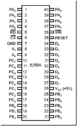
1. Draw the pin diagram of PPI 8255.

Ans. The pin diagram of 8255 is shown in Fig. 9a.1


8255 Programmable Peripheral Interface 7-59-52 PM

Fig. 9a.1: 8255 Pin diagram (Source: Intel Corporation)

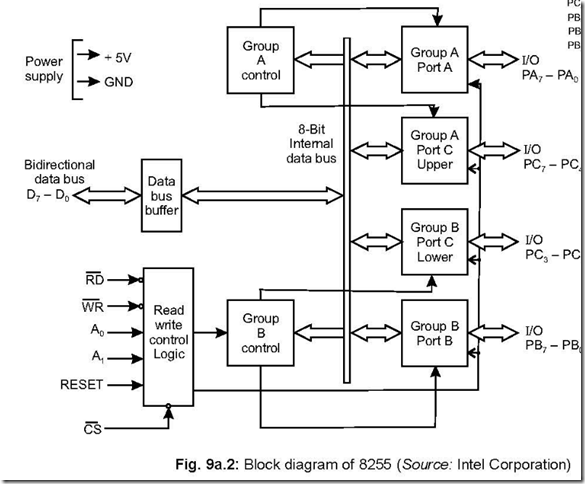
2. Draw the block diagram of 8255.

Ans. The block diagram is shown in Fig. 9a.2.

8255 Programmable Peripheral Interface 8-00-23 PM


3. How many ports are there in 8255 and what are they?

Ans. Basically there are three ports in 8255, viz., Port A, Port B and Port C, each having 8 pins. Again Port C can be divided into Ports Cupper and Port Clower— each having four pins i.e., a nibble. Thus 8255 can be viewed to have four ports—Port A, Port B, Port Cupper and Port Clower.

4. What pins are associated with Read/Write control logic block?

Ans. There are six pins associated with Read/Write control logic block. These are CS, WR,

A0, A1, Reset and CS signals.

5. In how many modes can 8255 operate?

Ans. PPI 8255 can operate in three modes. (a) Mode 0 (b) Mode 1 and (c) Mode 2.

Apart from the above, there is another mode called BSR mode (Bit Set/Reset mode).

6. Distinguish between the three modes of 8255.

Ans. The three modes are Mode 0, Mode 1 and Mode 2. These are I/O operations and selected only if D7 bit of the control word register is put as 1.

The three operating modes of 8255 are distinguished in the following manner:

Mode 0: This is a basic or simple input/output mode, whose features are:

z Outputs are latched.

z Inputs are not latched.

z All ports (A, B, CU, CL) can be programmed in either input or output mode.

z Ports don’t have handshake or interrupt capability.

z Sixteen possible input/output configurations are possible.

Mode 1: In this mode, input or outputting of data is carried out by taking the help of handshaking signals, also known as strobe signals. The basic features of this mode are: z Ports A and B can function as 8-bit I/O ports, taking the help of pins of Port C.

* I/Ps and I/Ps are latched.

* Interrupt logic is supported.

* Handshake signals are exchanged between CPU and peripheral prior to data transfer.

* In this mode, Port C is called status port.

* There are two groups in this mode—group A and group B. They can be configured

separately. Each group consists of an 8-bit port and a 4-bit port. This 4-bit port is used

for handshaking in each group.

Mode 2: In this mode, Port A can be set up for bidirectional data transfer using handshake signals from Port C. Port B can be set up either in mode 0 or mode 1.

The basic operations of the three modes are shown below:8255 Programmable Peripheral Interface 8-00-57 PM7. Which word determines the operating mode of 8255? Ans. A single control word determines the operating mode of 8255.

8. For data transfer using 8255, when mode 0 should be selected? Ans. When unconditional or non-handshaking I/O is required, mode 0 is chosen.

9. How many categories of handshake signals are there? Which is advantageous? Ans. Handshake signals can be used with either (1) status check I/O or (2) Interrupt I/O.

In the status check I/O, the CPU gets tied up in a loop until the status of the I/O

becomes ready while it is the I/O device which interrupts the CPU in interrupt I/O.

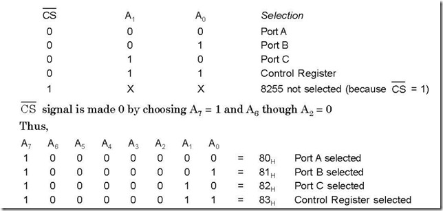
10. Explain how the different ports and control words are selected for 8255.

clip_image006Ans. The two address lines, along with CS signal, determine the selection of a particular port or control register. This is explained below:

8255 Programmable Peripheral Interface 8-01-19 PM


11. What is BSR mode and what are its characteristics?

Ans. BSR mode stands for Bit Set Reset mode.

The characteristics of BSR mode are:

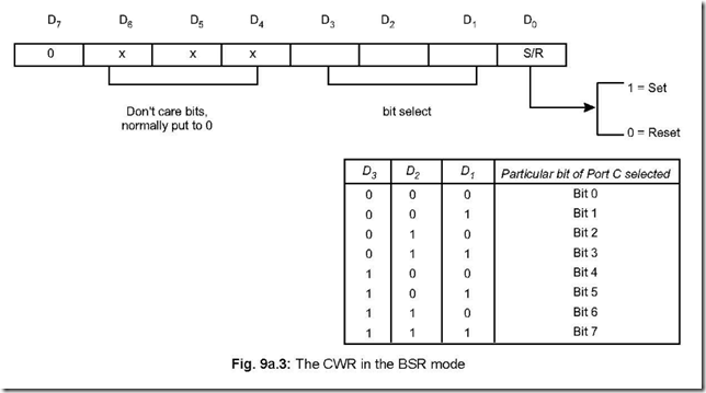
* BSR mode is selected only when D7 = 0 of the Control Word Register (CWR).

* Concerned with bits of port C.

* Individual bits of Port C can either be Set or Reset.

* At a time, only a single bit of port C can be Set or Reset.

* Is used for control or on/off switch.

* BSR control word doesn’t affect ports A and B functioning.

12. Discuss the control word format in the BSR mode.

Ans. The content of the control word register will be as follows, when used in the BSR mode and selects (either Sets or Resets) a particular bit of Port C at a time.


8255 Programmable Peripheral Interface 8-01-43 PM

13. Write a BSR control word to set bits PC7 and PC0 and to reset them after 1 second delay.

Ans. To set or reset any particular bit of Port C in the BSR mode, the control word register is to be appropriately loaded. The above is done by loading the accumulator and sending the same to the control register (i.e., by sending the same to the address of the control register). The address of control word register (CWR) is 83H.

Program:

MVIA, 0FH (Accumulator loaded with 0FH to set PC7 bit of Port C) OUT 83H (This sets PC7 bit of Port C)

MVIA, 01H (Accumulator loaded with 01H to set PC0 bit of Port C) OUT 83H (This sets PC0 bit of Port C)

CALL DELAY (Assume the DELAY is for 1 second)

MVIA, 00H (Accumulator loaded with 00H to reset PC0 bit of Port C) OUT 83H (This resets PC0 bit of Port C)

MVIA, 0EH (Accumulator loaded with 0EH to reset PC7 bit of Port C) OUT 83H (This resets PC7 bit of Port C)

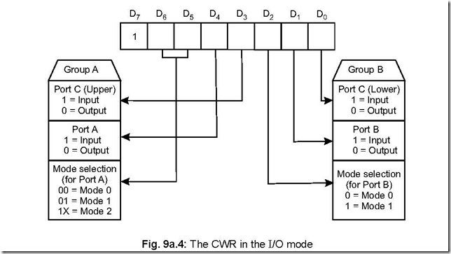
14. Show the control word format for I/O mode operation of PPI 8255. Ans. The control word format, when 8255 is operated in I/O mode, is shown below:

For 8255 PPI to be operated in I/O mode, D7 bit must be 1.

The three ports are clubbed into two groups—Groups A and B. Group A consists of

Port A and CU. Port A can be operated in any of the modes—0, 1 or 2. Group B consists of Port B and CL. Here Port B can be operated in either mode 0 or 1.

8255 Programmable Peripheral Interface 8-02-10 PM


15. What happens when RESET pin of 8255 is made high?

Ans. When a 1 is applied on RESET pin of 8255, the three ports are put in the input mode.

All flip-flops are cleared and interrupts are reset. This condition is not altered even when

RESET goes low. 8255 can then be programmed in any mode by appropriately loading

the control word register. The mode operation can be changed by altering the content

of the control word register, whenever needed.

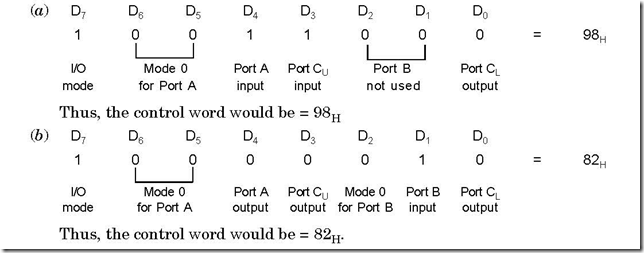
16. Write down the mode 0 control words for the following two cases:

(a) Port A = Input port, Port B = not used, Port CU = Input port and Port CL

= Output port.

(b) Port A = Output port, Port B = Input port, Port C = Output port Ans. The control words for the two cases will be as follows:


8255 Programmable Peripheral Interface 8-02-48 PM

17. In mode 1 what are the control signals when ports A and B act as input ports.

Discuss the control signals. Draw the timing waveforms for such a strobed

input.

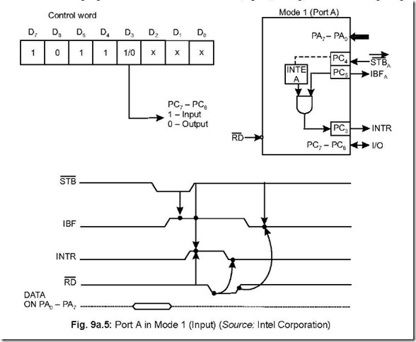
Ans. The following are the control signals when ports A and B act as input ports (under mode 1) STBA , IBFA, INTEA for Port A and STBB , IBFB, INTEB for Port B, respectively. The mdetails about the input control signals are discussed below:

z STB (Strobe input): This is an active low signal generated by a peripheral device.

When a peripheral device has some valid data, it sends the same via Port A or B and

sends a low STB signal. This data is accepted by 8255 and it generates a IBF and INTR

(provided INTE is set previously).

z IBF (Input buffer full): On receipt of STB signal from peripheral device, data is stored

in 8255 by its input latch. In its turn, 8255 generates a high IBF. IBF is reset when CPU reads the data.

z INTR (Interrupt request): This active high output signal is generated only if STB , IBF

and INTE are all set at the same time. This signal interrupts the CPU via its INTR (pin no. 10 of 8085).

z INTE (Interrupt Enable): This is an internal F/F which can be set/reset using the BSR mode. It must be set if INTR signal is to be effective.

The following figure shows Port A in Mode 1 (input), along with the timing diagrams.


8255 Programmable Peripheral Interface 8-04-44 PM

18. In mode 1, what are the control signals when ports A and B act as output ports.

Discuss the control signals. Draw the timing waveforms for such a strobed

output.

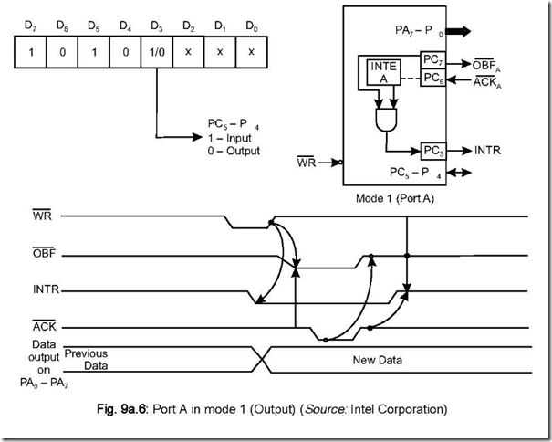
Ans. The following are the control signals when ports A and B act as output ports (under mode 1) OBFA , AC A , INTEA for Port A and OBFB , ACK B , INTEB for Port B

respectively.

The details about the output control signals are discussed below:


* OBF (Output buffer full): This is an active low output signal. This signal becomes low

when the CPU writes data into the output latch of 8255. This output signal from 8255, which goes to a peripheral, indicates to the peripheral that the data on the output latch of 8255 is ready to be read.

*ACK (Acknowledge): When data reading by the peripheral from the output latch of

8255 is complete (i.e., the peripheral has accepted the data), it (the peripheral) outputs ,a low signal which is connected to the ACK (input signal) pin of 8255. On receipt of this low signal by 8255 (from peripheral), the OBF line of 8255 goes high.

*INTR (Interrupt): This signal is set only if OBF , ACK and INTE (internal F/F) are all at high(1) state. This output signal from 8255 goes to INTR (pin 10 of 8085) to interrupt the CPU. The INTR signal is reset on the falling edge of WR .

* INTE (Interrupt Enable): This is an internal F/F which can be set/reset in BSR mode.

This must be set if INTR signal is to be effective.

he following figure shows Port A in mode 1 (output), along with the timing waveforms.

8255 Programmable Peripheral Interface 8-05-07 PM


19. In mode 1, what are the methods available for data transfer? Which method is advantageous?

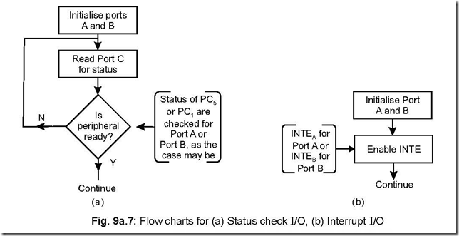
Ans. In mode 1, data transfer is possible involving 8255 when it is programmed to function either in (a) Status check I/O (also called Program Controlled I/O), (b) Interrupt I/O (also called Interrupt Controlled I/O).

8255 Programmable Peripheral Interface 8-05-48 PM

In status check I/O, CPU continues to check the status of IBFA or IBFB until they are high. This is done by reading the status word (port C) to check (PC5 for IBFA and PC1 for IBFB) for existence of IBF. It is known as ‘polling’ (reading) the status word. Here it is assumed that both Ports A and B act as input ports.

In interrupt I/O scheme, the status of either INTRA or INTRB (as the case may be) will have to be ascertained to know the port (A or B) which has requested (interrupted) for service. This is done by reading the status of INTRA (PC3) or INTRB (PC0) of the status word. Here again, it is assumed that both ports A and B act as input ports.

Status check I/O is disadvantageous because in this the CPU gets tied up in the loop until the IBF line (IBFA or IBFB, as the case may be) goes high.

20. Show the mode 1 status word format and discuss.

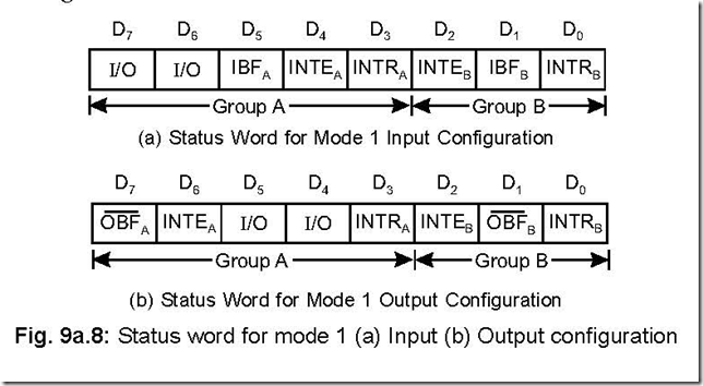
Ans. There are two mode 1 status word formats—one for input configuration and the other for output configuration. These are shown below:

8255 Programmable Peripheral Interface 8-06-34 PM


The mode 1 status format (either input or output configuration) can be read by an input read of Port C.

When 8255 is operated in mode 1, the processor has two choices — either polling or interrupt scheme—this is true irrespective of whether data is inputted to the CPU or otherwise.

When data is inputted (i.e., from peripheral to CPU), the CPU can poll (status check) the IBF line for presence of valid data. Else the processor can be interrupted via the INTR line. To know whether INTRA or INTRB has interrupted can be ascertained by reading the Port C for status of INTRA (bit D3) or INTRB (bit D0).

Again, when data is outputted (by CPU to 8255), again two choices are there. The

CPU can poll the OBF or else be interrupted by INTR line.

If interrupt driven scheme is followed, then INTE (either INTEA or INTEB) has to be previously set in BSR mode.

A confusion arises when interrupt driven I/O scheme is undertaken. For input

configuration, it is seen that STBA signal is connected to PC4 and INTEA is controlled by PC4. For Port B, the corresponding bit is PC2—i.e., STBB is connected to PC2 and INTEB is also controlled by PC2. But this poses no problem because INTE is set/reset in

BSR mode and the BSR control word has no effect when ports A or B are set in mode 1.

21. Discuss the mode 2 of PPI 8255 in brief.

Ans. This mode is usually used for transferring data between two computers.

When operated in mode 2, only Port A can be used as a bidirectional 8-bit I/O bus, using PC3 – PC7 for handshaking. Port B can be programmed only in mode 0 (PC0 – PC2 as input or output) or in mode 1 (PC0 – PC2 used as handshaking signals).

22. How many possible combinations of 8255 would be there when it is operated in mode 2.

Ans. Only Port A can be operated in mode 2 and Port B in either mode 0 or mode 1.

Thus, there would be four possible combinations in mode 2. These are:

(a) Mode 2 and Mode 0 (input)

(b) Mode 2 and Mode 0 (output)

(c) Mode 2 and Mode 1 (input)

(d) Mode 2 and Mode 1 (output)

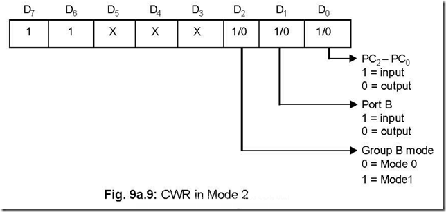
23. Discuss the Mode 2 control word.

Ans. The mode 2 control word is as shown below:


8255 Programmable Peripheral Interface 8-06-59 PM

This control word is to be loaded into the control port to configure 8255 in mode 2. Bit D0 of control port determines the I/O operations of PC2 – PC0. D1 bit indicates the Port B input/output operation whereas bit D2 determines Group B to be either in mode 0 or in mode 1 operation.

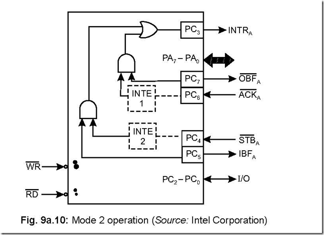
24. Draw Port A and the associated control signals when 8255 is operated in mode 2.

Ans. This is shown in the following figure:

8255 Programmable Peripheral Interface 8-07-23 PM


25. What are the output control signals in mode 2 and discuss them?

Ans. The output control signals in mode 2 are OBF , ACK and INTE 1. These control signals are discussed below: OBF stands for output buffer full, an active low signal. In its active condition (i.e., low), it indicates that the CPU has written data into Port A. ACK , an active low signal, stands for acknowledge. This acknowledgement signal is generated by a peripheral and it enables the tri-state output buffer or Port A and makes Port A data available to the peripheral.

INTE 1 is an internal F/F associated with output buffer full. INTE 1 can be used to enable or disable the interrupt (INTR) by setting or resetting PC6 in BSR mode.

26. What are the input control signals in mode 2 and discuss them?

Ans. The input control signals in mode 2 are STB , IBF and INTE 2. These control signals

are discussed below:

STB (strobe input), an active low signal, enables Port A to latch the data available

at its input. This happens if STB = 0.

IBF (Input buffer full), an active high signal, indicates the data has been loaded into the input latch of Port A. This happens if IBF = 1.

INTE 2 is an internal F/F associated with input buffer full. INTE 2 can be used to enable or disable the interrupt (INTR) by setting or resetting PC4 in BSR mode.

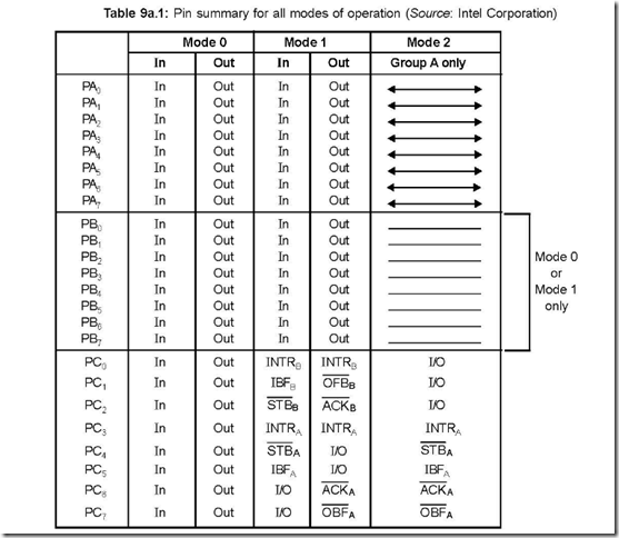
27. Draw a table that summarises the pin functions of Ports A, B and C for various modes of operation.

Ans. The following table shows the pin summary of Ports A, B and C for various modes of operation.

8255 Programmable Peripheral Interface 8-07-45 PM

28. What are the status of Port A outputs until they are enabled.

Ans. Port A outputs remain in the tri-state condition until they are enabled. This enabling is done by a low on the ACK signal generated by a peripheral.

29. On which line interrupts are generated in mode 2 for both input and output operations?

Ans. The same (INTRA) is generated on PC3 line, for both input and output operations.

30. Draw the status word in mode 2 and discuss.

Ans. The status word in mode 2 is as shown:

8255 Programmable Peripheral Interface 8-08-07 PM

This status word is accessed by reading Port C. D7 – D3 bits of the status word carry the status of OBFA , INTE 1, IBFA, INTE 2, INTRA. The status of the remaining three

bits i.e., D2 – D0 depend on the mode setting of Group B. If Group B is programmed to be in mode 0, then D2 – D0 are simply PC2 – PC0 (simple I/O). But if Group B is in mode

1, then the three bits D2 – D0 carry the information about the control signals for Port

B—and they depend on whether B is acting as an input port or output port.

31. What are the types of devices with which data transfer takes place via the 8255 PPI?

Ans. The input devices from which data are read and delivered to the microprocessor via the input ports of 8255 PPI are ADCs, keyboards, control signals from process devices, paper tape readers, etc.

The output devices to which data are delivered via the output ports of 8255 are DACs, printers, video display, plotters, etc.

32. What kind of functions do the input and output ports play?

Ans. A port, whether an input or an output port, is a set of D F/Fs consisting of several pins in parallel. When used as input pins, they act as buffers and when used as output pins, they act as latches.


Memory

Memory

1. What is a memory?

Ans. A memory is a device that stores information in electrical, magnetic or optical form. A

µC based system, which operates on digital logic, holds binary information. Semiconductor

memories are used in µC based system.

2. Why semiconductor memories are used as main memories in mC based systems?

Ans. Semiconductor memories have become very popular and widely used because of their high reliability, low cost, high speed and ease with which memory size can be expanded.

3. What is the use of memory in a mC based system? Ans. Memories are used for storage of both program and data.

4. In how many categories memories can be classified? Give examples and distinguish between them.

Ans. It can be categorised into two ways:

z Primary memory or main memory or working memory.

z Secondary memory or auxiliary memory or mass storage.

RAM and ROM comprise the primary memory while magnetic tapes, magnetic disks,

floppy disks or compact disks (CDs) are examples of secondary memory.

Distinction between the two types of memories are:

Table 8.1: Comparison between primary and secondary memory

S. No.

Primary memory

Secondary memory

1.

Can store less amount of data.

1.

Can store huge amount of data.

2.

Faster speed of operation.

2.

Slower speed of operation.

3.

Can be volatile/non-volatile in nature.

3.

Always non-volatile in nature.

4.

Program/data used by the programmer

4.

Not used for such purpose.

are resident in the main memory.

5.

Can be directly accessed by CPU.

5.

Cannot be directly accessed by CPU but

can be accessed through I/O ports or in

a serial format using hardware/software.

6.

If the CPU has n address lines, a

6.

No such relation exists.

maximum of 2n main memory locations

can be accessed.

7.

Less costly.

7.

Costlier than main memory.

5. What is the basic memory operation?

Ans. ‘Read’ and ‘Write’ are the basic operations performed by a memory device. The process of storing data into memory is called ‘Writing’ and retrieving data/instruction from the memory is called ‘Reading’. Each memory location is identified by a particular address corresponding to the memory location. For reading or writing data, the particular memory location is to be identified by its address first and then only reading/writing is done.

6. What is a cell?

Ans. Memories are made of storage elements, which can store one bit of data. Each storage element is called a cell. In semiconductor memories, flip-flops act as storage elements.

7. What is meant by ‘working length’ of a memory?

Ans. At each memory location, which is identified by its address, one or more number of bits can be stored. The number of bits that a particular memory location can store is known as working length of a memory. This also goes by the name of word size.

8. What is meant by “access time” of a memory? On which does it depend?

Ans. It is the time required to perform a read operation. Putting another way, it is the time between the memory receiving a new address and putting out the memory content on its output. This time is symbolised by tacc.

9. What is a sequential access memory (SAM)?

Ans. It is a kind of memory for which tacc is not constant for all memory locations/positions.

An example of a SAM is a magnetic tape backup. The latter the data is stored, the more

the tacc time for such a data. SAM is used only when data retrieval is always sequential in nature.

10. What is a volatile memory?

Ans. It is such a memory whose stored information is lost when electrical power is removed.

Semiconductor memories may be volatile/non-volatile in nature, while magnetic memories are non-volatile.

11. A semiconductor memory is specified as 4 K × 8. Indicate the number of words, word size and total capacity of this memory.

Ans. Total number of words or memory locations that can be accessed is

= 4 K = 4 × 1024 = 4096

Word size = 8

and total capacity of the memory is

= 4096 × 8 = 32768

= 32,768 bits.

12. Diagrammatically show a 1 K × 8 memory,indicating the relevant pins.

Ans. The following figure shows the diagrammatic representation of a 1 K × 8 memory. ]

The memory will be selected only if CS (chip CS select) signal is low. 1 K represents 1024 memory 8 address locations so that 10 number of address O inputs (A0– A9) are required. I0– I7 and O0 – O7 (both 8 pins) represent respectively data inputs and outputs.
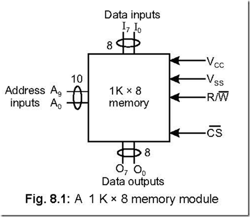
Memory 6-48-42 PM


13. Show the different versions of semiconductor memories available.

Ans. Basically semiconductor memories can be RAM (Random Access Memory) or ROM (Read Only Memory)—both of which are available in bipolar technology or MOS (Metal Oxide Semiconductor) versions. The different versions available are:
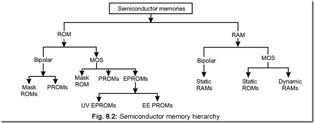
Memory 6-49-21 PM

14. What are the characteristic features of a RAM? Ans. The essential features of a RAM are:

1. It is volatile in nature—i.e., when the power is switched off, data stored at the different memory locations are totally lost.

2. When data/instruction is written at a memory location, previous data stored at this location is destroyed and replaced by the new data.

3. When data/instruction is read from an address location, the existing data is not lost (destroyed).

15. What is a CAM?

Ans. It stands for Content Addressable Memory. It is a special purpose RAM which performs association operation, in addition to read/write operations.

16. What is a PLA? What are the advantages of using a PLA?

Ans. A PLA stands for ‘Programmable Logic Array’. It is a non-volatile random access storage device. It can be used for implementing random logic circuitry and ROMs.

A PLA consists of two arrays (AND and OR), an input buffer and an output buffer.

The main advantages of using a PLA are: 1. Fastest access time 2. High switching

speed 3. Compact circuitry 4. Implementing random logic circuitry.

The block diagram of a PLA is as follows:
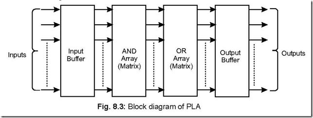
Memory 6-49-57 PM

17. Applicationwise, write down the differences between RAM and ROM.

Ans. RAMs are used for writing/development of a program while ROMs are used for such programs which are repetitively required in a program—for example hexa-decimal conversion table, display program, time delay program and most importantly programmed instructions for system initialisation and operation.

18. What are the incompatibilities that may arise when memory devices are interfaced with mP? How are they removed?

Ans. The incompatibilities are: electrical, speed and bus.

Electrical incompatibility is removed by using bidirectional and unidirectional bus drivers.

Speed incompatibility is overcome by either slowing down the CPU clock or by

inserting wait states.

Bus incompatibility arises because of multiplexed address-cum-data bus, Read-Write signals differing for CPU and memory. The bus incompatibility can be removed by using extra hardware.

19. What are bit and byte organised memories?

Ans. For a 2n × m memory, where n is the number of address lines such that a maximum of 2n memory locations can be accessed and m is the word length, if m is 1 then the memory is said to be bit organised, whereas if m is 8, then the memory is said to be byte organised.

20. Mention the essential features of Mask programmable ROM and PROM. Ans. The essential features of these two are tabulated as follows:

Table 8.2: Comparison between mask programmable ROM and PROM

S. No.

Mask programmable ROM

PROM

1.

Manufactured by making special masks.

1.

Manufactured by blowing fusible

nichrome wire links.

2.

Programmed at the factory premises.

2.

Programmed by the user.

3.

No reprogramming possible.

3.

No reprogramming possible.

4.

Less costly.

4.

More costly.

21. What is a EPROM? Mention its two types and compare.

Ans. EPROMs are manufactured with NMOSFET technology with an isolated gate structure.

There are two types of EPROM. These are:

UVEPROM : Ultraviolet erasable programmable Read-only-Memory EEPROM : Electrically erasable programmable Read-only-Memory (also known

as EAPROM)

A comparison between UVPROM and EEPROM is made hereunder:

Table 8.3: Comparison between EEPROM and UVPROM

S. No.

EEPROM

UVPROM

1.

Can be erased and programmed with

1.

Can be erased and programmed with

electrical signals.

ultraviolet light.

2.

The voltage on the floating gate structure

2.

The photo current from the insulated

allows storage of information.

gate structure allows storage of

information.

3.

Higher speed of operation.

3.

Lower speed of operation.

4.

More expensive.

4.

Less expensive.

5.

Relatively easy to manufacture.

5.

Relatively difficult to manufacture.

6.

Erasing takes several minutes.

6.

Erasing takes several minutes.

7.

In-situ erasing possible.

7.

In-situ erasing not possible.

8.

Byte wise erasing possible.

8.

Erasing wipes out the entire memory.

9.

Less packing density.

9.

More packing density.

22. Name some of the application areas of ROM.

Ans. ROM has applications in many areas. Some of these are: bootstrap memory, firmware, data converters, function generators, data tables, etc.

23. What is a firmware?

Ans. A set of program/data must be made available to a microprocessor based system whenever it is powered on. This program/data is stored in ROM in what is called a firmware.

Laptop computers, PCs, etc. store their operating system programs and language interpreters (like PASCAL, BASIC, etc.) in ROM firmware.

24. What is a boot strap memory?

Ans. Most large computers store their operating system in external mass memory like

magnetic disk. For such computers, a small program, called the boot strap program, is stored in the ROM area of the computer. On powering such a computer, the bootstrap program is first executed which then loads the operating system programs from magnetic disk into the main (internal) memory of the computer. The OS is then run by the computer so that it becomes ready to accept user commands, this ‘start-up’ process is called ‘booting of the system’.

25. What is a flash memory?

Ans. This is an alternative to EPROMs and EEPROMs. It provides for very fast read access, in-circuit erasability. Its density almost matches that of EPROM, at the same time it is cost effective also. They consume less power and are able to withstand severe shock and vibration.

Most flash memory chips erase all the cells in the chip, although some newer version of flash memory chips has sectorwise erase option, i.e., 512 bytes of information can be erased at a time.

Typical values for memory write (per byte) are 10 ms, 100 ms and 5 ms for flash type, EPROM and EEPROM, respectively.

Flash memories are used in digital cellular phones, LAN switches, embedded

controllers, digital set-up boxes, etc.

26. What are the different types of SAMs?

Ans. SAM stands for Sequential Access Memory. Its different versions are: Shift Memory, Charged Coupled Devices (CCDs) and Bubble memories.

27. What kind of memory device is a CCD?

Ans. It is volatile type memory device, whose contents can be accessed in a serial manner.

28. Name the basic storage element in a CCD.

Ans. The basic storage element in a CCD is a MOS capacitor.

29. Mention the operations involved in a CCD memory. Ans. The main operations involved are:

z Converting a digital input signal into charge.

z Transferring the charges in a sequential manner.

z Charges at the outputs are converted back into digital form.

30. Discuss Bubble Memory.

Ans. Magnetic bubble memory is a solid state device. It is highly reliable, small in size, light in weight and its power consumption is low. Its access time is high—i.e., it is a slow device. A typical figure is 100 k bits/second.

In this type of memory, data is stored in magnetic bubbles. This is done in a thin film of magnetic material. A ‘1’ is represented by the presence of a bubble while the absence signifies a logical ‘0’.

It is a non-volatile semi random access type memory. Its readout is non-destructive in nature.

A bubble memory contains several loops, each loop of which contains a large number of bits. For read or write operation to be done, each loop possesses a 1-bit viewing window.

INTEL 7110 is a bubble memory chip having 1 M bits storage capacity while INTEL 7114 has a 4M bits capacity.

31. Explain how the entire addressable memory space of 8085 can be conceived of the pages of a book?

Ans. The entire addressable memory space is 216 = 65,536 lines, because 8085 has 16 address lines. This is arbitrarily divided into 256 pages (0 to 255 pages) with each page consisting of 256 lines (0 to 255 lines), as shown in Fig. 8.4
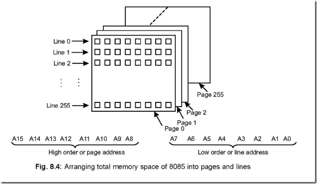
 

Memory 7-10-31 PM

The sixteen address lines can be divided into higher (A15 – A8) and lower (A7 – A0) eight bits. On each page there are 256 lines defined by the lower byte (A7 – A0), while each page of the book is defined by the different combinations of the upper byte (A15 – A8).

The following figure shows an arbitrary but convenient way of showing the total

memory space, with each block consisting of 4 K lines i.e., 16 pages.
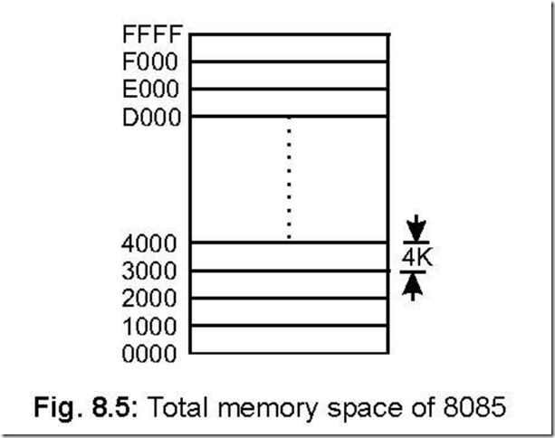
 

Memory 7-10-46 PM


32. Mention the memory capacities corresponding to the number of address lines 10, 11, 12 16.

Ans. The memory capacities corresponding to the number of address lines 10, 11, … 15, 16 are 1 K, 2 K, 4 K, 8 K, 16 K, 32 K and 64 K, respectively.

33. What is a dual-port RAM? Mention its use.

Ans. It is a RAM having separate input and output pins. Because separate input and output pins are used (unlike normal RAM, in which data bus is bidirectional), it is used in high speed applications like the video RAM in a PC. In such a case the system bus feeds the RAM input with new informations while the video card reads from the RAM to constantly refresh the screen.

34. What is a NVRAM? Mention its use.

Ans. It stands for non-volatile RAM and is made by the combination of static RAM and an EEPROM. The memory structure of static RAM and EEPROM are mirror images of each other. When powered, NVRAM behaves as a normal RAM. When there is a power failure, RAM data is saved in EEPROM in less than 4 ms. On restoration of power, the reverse

clip_image021process occurs with contents of EEPROM sent back to RAM. Two pins STORE and

clip_image022RECALL of the NVRAM are used to store data in EEPROM and transfer it back to RAM respectively, both these transfers occurring on ‘low’ on the two pins.

The advantage of using an NVRAM is that a battery backup is not required to save

the RAM data in case of power failure.

The NVRAM finds its use in information storage such as time, date, monitor setting and other computer configurations.

35. What is a memory map?

Ans. A microcomputer system uses a mix of ROM, RAM for its addressable memory space.

Some of the memory space may be left unimplemented or open.

The memory map is a guide showing how the entire system memory has been allocated to ROM, RAM so that any future memory expansions can be executed effectively.

36. Draw a static RAM (SRAM) cell and explain its operation.

Ans. A standard SRAM consists of six transistors connected to form a R-S flip-flop. A SRAM cell is shown below. The transistors Q1 and Q2 form the cross-coupling transistors required for latching.
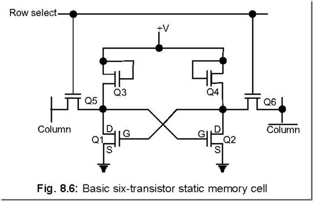
Memory 7-11-13 PM


Data is written into the cell by applying the data and its complement at the column and column inputs respectively, with Q5 and Q6 in the ON condition. Data can be read

out from the column line after Q5 and Q6 are enabled.

Some of the characteristics of a SRAM cell are:

* It is volatile—i.e., data is lost on switch-off.

* When powered, the cell may assume either 1 or 0 state.

* Easy interfacing possible.

* No special timing circuits required.

* Bit density is low compared to DRAM.

37. Draw a dynamic RAM (DRAM) cell and explain its operation.

Ans. A basic DRAM storage cell is shown below:

When column (sense) and row (control) lines go high, the MOSFET conducts and charges the capacitor. Again when the column and row lines go high, the MOSFET opens and the capacitor retains its charge. Thus, it can store a single bit. Since only a single MOSFET and a capacitor are employed to store a bit, the DRAM density is high. Here, the MOS transistor acts as a switch.

Some of the characteristics of a DRAM cell are

* Higher packing density.

* Charge leaks, thus refreshing needed.

* Extra hardware needed to implement refreshing operation.

38. Compare a SRAM and DRAM cell.

Ans. The comparison is shown in a table 8.4:

Table 8.4: Comparison between Static and Dynamic RAM cells

S.No.

Static memory

Dynamic memory

1.

Stored data is retained as long as power

1.

Stored data gets lost and repeated

remains ON.

refreshing is required.

2.

Stored data do not change with time.

2.

Stored data changes with time.

3.

Consumes more power.

3.

Consumes less power than static

memory.

4.

Expensive.

4.

Less expensive.

5.

These memories have less packing density.

5.

Higher packing density.

6.

These memories are not easy to construct.

6.

Simpler in construction.

7.

No refreshing required and easy in operation.

7.

Refreshing required with additional

memory circuitry and hence complicated

operation.

8.

No maintenance.

8.

Maintenance needed.

39. What are the different types of DRAMS available. Briefly describe their operations.

Ans. The different types of DRAMS available are as follows: SDRAM, FPM DRAM, EDO DRAM, DDRS DRAM, SL DRAM, and DR DRAM.

Here is a brief description about the different DRAMS.

SDRAM: It stands for synchronous DRAM. Internally, these DRAMs are organised into two banks for very fast reading. Its internal circuit is quite complex because of various operations needed such as burst length, sequential or interleaved data, self-refreshing,

CAS -before- RAS, etc.

SDRAMs transfer data in rapid-fire bursts of several sequential memory locations on the same page. The first memory accessing requires maximum time because of latency problem. After that data are transferred and clocked out by the bus system clock.

FPM DRAM: It stands for fast page mode DRAM. Within the same page it allows fast random memory accessing. Fast memory accessing is possible since to access memory locations on the same page, only the lower address lines are to be changed.

EDO DRAM: It stands for extended data output DRAM. It is a bit faster than FPM DRAM. In the case of EDO DRAM, the memory controller can output the next address while the current word is being read out from its output lines. This is not so in case of FPM DRAM.

DDRS DRAM: It stands for double data rate SD RAM.

The doubling of data rate over SDRAM is because of transfer of data on the rising and falling edge of the system clock.

SL DRAM: It stands for synchronous link DRAM.

It is an improvement over DDRS DRAM. Like DDRS DRAM, it also transfers data on the rising and falling edge of system clock with bus speed of around 200 MHz.

DR DRAM: It stands for Direct Rambus DRAM.

It is a proprietory of Rambus Inc. It utilises a newer approach to DRAM technology and is currently under development. Within this DR DRAM, more control has been incorporated for relisation of newer technology.

40. Why DRAM chips do not have CS signal?

Ans. The CS (chip select signal, normally low) signal either selects or deselects a chip as per

its status (0 selects and 1 deselects). DRAM chips have a (row address strobe) and a CAS (column address strobe), which together perform the function of CS signal.

Several address lines go to a row address decoder and several others go to a column address decoder. The output of these two decoders ( RAS and CAS ) then select a

particular cell of the corresponding row and column addresses in which read or write operation is then performed—like a static RAM.

41. What kinds of memory expansions are possible by combining memory chips?

Ans. By combining memory chips, two kinds of expansions are possible—one is word size expansion and the other is capacity expansion.

By word size expansion is meant that each memory location can be expanded say from 1 nibble to 1 byte, while by capacity expansion is meant the expansion of a 2 KB memory into, say a 8 KB or 16 KB memory unit.

42. What is the principle of operation of an optical memory?

Ans. An optical disk memory operates on the principle of reflection or scattering of a very narrow laser beam of the optical surface having microscopic size bubbles or pits. These represent logical 1’s.

43. What are the advantages of optical memory?

Ans. These kind of memories have large memory, relatively low in cost, very less dust-prone and access time comparable to hard disks.

44. Name the basic types of optical disk memories. Ans. The basic forms of optical disk memories are as follows:

* WORM or Write once read memory

*CD-ROM or Compact disk ROM

* OROM or Optical ROM

Out of the above, OROM can be written several times, while the contents of CD- ROMs and WORMs cannot be erased.

45. Name several commercially available EPROMs.

Ans. Several EPROMs are available commercially, which are listed below in a tabular form.

Out of these, the IC types 2708, 2716, 2732–although in use today, are increasingly being replaced by the newer varieties because of higher bit capacity.

ICs

No. of bits (in K)

Memory Organisation type

Erasing type

Output after erasing

2708

8

1 K × 8

UV erasable

FF H

2716

16

2 K× 8

2732

32

4 K × 8

2764

64

8 K × 8

27128

128

16 K × 8

27256

256

32 K × 8

27512

512

64 K × 8

46. Design a memory having size 16 × 8 from 16 × 4 memory modules.

Ans. A 16 × 8 memory module indicates that it can address 16 different memory addresses, each address location can store 1 byte of data/instruction. The design is given below:
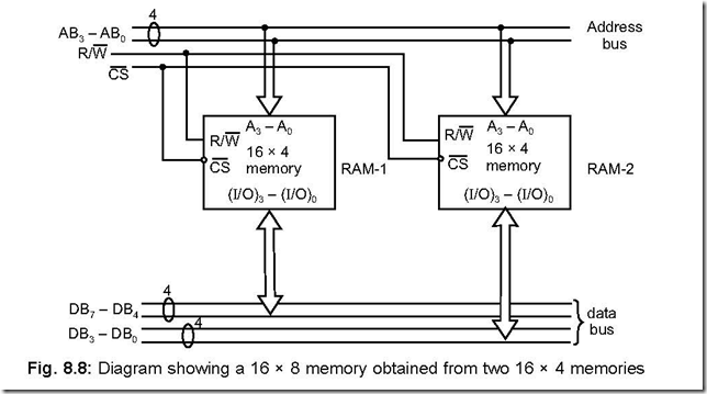
Memory 7-12-51 PM

The address lines AB – AB can address 16 different addresses (from 0000 to 1111)

and connected to the two RAMs as shown. Chip selection is on the basis of CS signal

while R/W signal governs of whether reading (from memory) or writing (into the memory)

is to be done.

Once a particular address has been selected (by AB3 – AB0 lines), DB7 – DB4 stores the upper nibble of data in the left RAM (RAM-1) while DB3 – DB0 stores the lower nibble of the data in the right RAM (RAM-2).

47. Develop a 32 × 4 memory module by combining two 16 × 4 memory chips.

Ans. The interconnections between the two 16 × 4 memory chips is shown below which yields a 32 × 4 memory module.
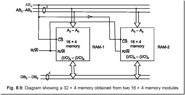
Memory 7-13-15 PM

The address line AB4 selects either RAM-1 or RAM-2. RAM-1 is selected when AB4 = 0 while RAM-2 is selected when AB4 = 1. The address ranges for RAM-1 is 00000 to 01111 while the same for RAM-2 is 10000 to 11111. Thus the combination acts as a memory having 32 different addresses, each of which can store 1 nibble (4 bits) of data/ instruction—controlled by DB3 – DB0 lines.

48. Explain ‘memory foldback area’.

Ans. It can be explained with the help of µP 8085 which can address 64 KB. Out of the 16 address lines available, 3 address lines (say AB15 – AB13) can be inputted to a 3 to 8 line decoder (it may be 74ALS138). Thus each of the 8 output decoded lines divides the entire 64 K into 8 nos. of 8 K address blocks. Suppose in the 8 K address block 2000–3FFF, a single 2 K × 8 RAM is used intended for operation from 2000–27FF. Since this is a 2 KB of memory, it can be addressed by 11 address lines (say AB10 – AB0). Now since the decoder output is active for 8 K addresses, hence the RAM will also respond to the remaining 6K addresses—resulting in the same contents of RAM to appear at the three address blocks 2800–2FFF, 3000–37FF and 3800–3FFF. Thus, the areas of the memory (here 2800 to 3FFF —a 6 K block) which are redundantly occupied by a device because of incomplete address decoding is known as ‘memory foldback area’.

49. Mention the facilities available when power fails in a mC based system.

Ans. A ‘power-fail’ situation may occur at any time of a micro computer’s operations. Critical applications—such as in process control systems, intelligent terminals, printers demand a stand by power supply when the main power fails.

There are several methods by virtue of which critical data can be saved in power fail situations. These are:

1. Back up batteries can hold critical data in RAMs when power fails, but problem arises if power remains off for a considerable time, i.e., the back up batteries are drained out after prolonged use and data will be lost.

2. Sometimes critical data are stored in non-volatile flash memories—thus no battery back up is needed. Thus in this case no problem is there even if power remains off for a considerable time. But the associated problem of a flash chip remains—i.e., erasing or writing one or few bytes is not possible, rather it is done sectorwise at a time.

3. The third approach involves storing of all critical data in high speed RAMs. When power fails, the CPU executes a short power down program stored in ROM. This allows the critical data from high speed RAMs to CMOS RAMs which are provided with battery back up. The ‘power down program’ is invoked by a circuit that senses the power failure situation.

On restoration of power, the CPU executes a power up program so that all critical data stored in back up devices are transferred back to system RAM—This is true for the above mentioned three cases.

50. Draw a typical memory read cycle and explain.

Ans. A typical memory read cycle is shown in Fig. 8.10.
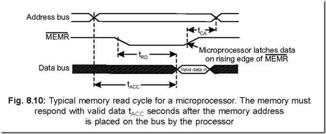
Memory 7-13-34 PM

The memory read cycle begins by outputting a valid address on its A0 – A15 address lines, after which the MEMR (active low) signal goes low, indicating that it is a memory read cycle. Then the microprocessor turns its internal data bus around so that it is now ready to receive data from the designated memory address.

The memory then places valid data on the data bus before the rising edge of MEMR . On the rising edge of the MEMR signal, the data is latched into the microprocessor signalling the end of the memory read cycle.

The three time periods shown in the figure are explained here.

tACC : This is the address access time. It corresponds to the maximum amount of time the memory needs to decode the address and place the selected data byte on the data bus.

tRD : This is the maximum amount of time after MEMR goes low that valid data is placed on the data bus by the designated memory.

tCA : This is the minimum amount of time after MEMR goes high before a new address appears on the address bus. If this minimum time is not met, it may be possible that a new memory address have started to put a new data byte on the data bus while the previous memory address was still outputting its own data. This will result in ‘bus contention’.

51. Draw a typical memory write cycle and explain. Ans. A typical memory write cycle is shown below:
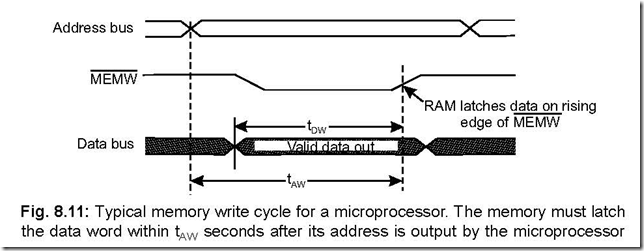
Memory 7-13-56 PM

The memory write cycle begins by outputting a valid address on its A0 – A15 address lines. Valid data is outputted on D7 – D0 lines early in the machine cycle which

corresponds to ‘data write set up time’. After this, the MEMW line goes low indicating

the memory write cycle.

The memory now has time up to the rising edge of MEMW to latch the data.

The two time periods shown in the figure are explained here.t : This is the minimum amount of time that valid address will be held on the bus
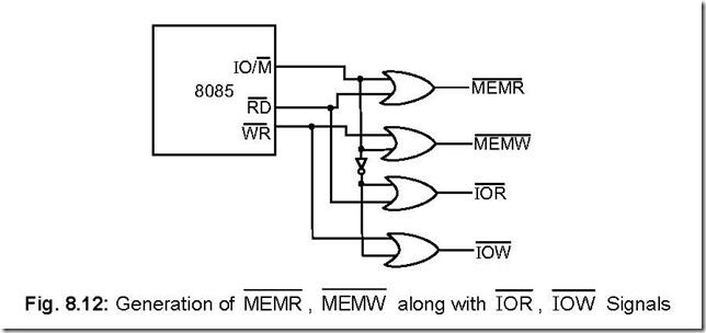
Memory 7-14-17 PM

53. Explain the working of a FIFO (first in first out) memory system.

Ans. In a RAM FIFO, the data word which is entered first is the one which is read out first.

The FIFO memory operation (reading or writing) is controlled by a address pointer register that keeps a track of location where from data are to be written and also the location where from data are to be read.

A FIFO RAM is used as a data rate buffer and is really useful for situations where

data takes place at widely diverging rates—e.g., from a computer to a printer or a

keyboard to the computer. In case of printing, data meant for printing are first stored

in a FIFO memory inside the printer. The printer then reads out the FIFO memory at

its own rate and printing done in the same order in which they were sent by the

computer.

Data rate buffers are also known as linear buffers.

54. How do circular buffers differ from linear buffers?

Ans. A circular buffer is a memory system which stores the ‘last’ n values entered, where n is the number of memory locations in the buffer.

A circular buffer, whose memory capacity is n, is addressed by a mod-n address counter. Thus, when the mod-n counter reaches the last (or highest) memory location, the next one to be addressed by the same would be the first address location.

Digital signal processing and digital filtering employ circular buffers as memory because their calculations are based on the recently taken data values.

55. What is usually meant by the speed of a memory?

Ans. Usually, the term ‘speed of a memory’ is meant the time needed to access the memory.

This is also known as ‘access time’.

56. Why it is necessary to decode an address from the microprocessor?

Ans. The address (to either memory or I/O device) is given out by the microprocessor. It is to be remembered that microprocessor is a sequential device—meaning that it can communicate (read or write) with only one device at any given instant. This is because the data bus, address bus and the control bus for all the devices connected to the microprocessor are common. Thus to communicate properly with a device (either memory or I/O), decoding of address is a must. Thus address decoding pinpoints a particular memory location or I/O.

57. What are the common address decoding techniques?

Ans. There are two kinds of address decoding techniques. These are

z Absolute Decoding—also known as Full Decoding.

z Linear Decoding—also known as Partial Decoding.

58. Describe the absolute decoding scheme.

Ans. In this scheme, all the higher order address lines are decoded to select the memory chips and a particular memory chip is selected only for a specified logic level on these address lines. The particular memory chip is not selected for any other logic level. The three higher order address lines go to the decoder 74LS138 which outputs Y0 …. Y7. While a low on Y0 selects only RAM-1, a low on Y7 selects RAM-8. Thus depending on the address line status on A15 – A13, only one memory chip is selected.

Memory 7-14-34 PM


59. Describe the linear decoding scheme.

Ans. In this scheme, the decoder logic is eliminated by using individual high order address lines to select particular memory chip. As shown in the figure, when A15 = 1, ROM-2 is selected while RAM-1 is selected for A15 = 0.

60. Compare absolute and linear decoding schemes.

Ans. The comparison between the two schemes are tabulated below in Table 8.5:
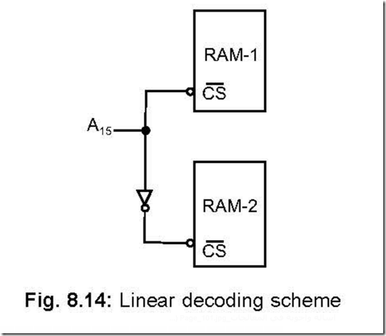
Memory 7-14-48 PM


Address Decoding

S. o.

Full address decoding (Absolute decoding)

Partial address decoding (Linear decoding)

1.

Used in large memory systems.

1.

Used in small memory systems.

2.

All higher order address lines are

2.

A few high order address lines are utilised

decoded to select the memory or I/O

to select individual memory or I/O chips.

device.

3.

Decoding logic requires more

3.

Hardware requirement for the same is very

hardware.

small and sometimes not required at all in

very small dedicated systems.

4.

No multiple addresses.

4.

Suffers from the drawback of multiple

addresses (also called shadow addresses).

5.

Higher cost of decoing.

5.

Lesser cost of decoding.

6.

Future memory expansion is easier.

6.

Future memory expansion is difficult.

7.

No bus contention problem.

7.

May suffer from bus contention problem—

may occur if more than one memory chip gets

selected because of wrong address generation.
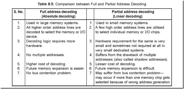
Memory 7-15-09 PM

61. What are meant by system memories and standard memories?

Ans. Some CPU manufacturers design memory chips compatible with their CPUs. This is done to reduce burden on extra hardware. Such memories are called system memories.

Again so many memory chips are manufactured which can be used with different

varieties of CPUs after overcoming the incompatibility problems. Such memories are called standard memories.

62. Compare system memories with standard memories.

Ans. The comparison between system memories and standard memories is tabulated below:

Table 8.6: Comparison between System Memory and Standard Memory

S. No.

System memories

Standard memories

1.

More expensive.

1.

Less expensive.

2.

May not be available from multiple

2.

May be available from multiple vendors.

vendors.

3.

Not available in a variety of

3.

Available in a variety of organisations,

organisations, sizes and speeds.

sizes and speeds.

4.

With a particular CPU, full compatibility

4.

For compatibility with respect to bus and

is there with respect to bus and speed.

speed, extra hardware is needed. Thus

Thus interfacing is easier and less

interfacing is relatively complex.

hardware needed.

5.

Easy to choose a system memory

5.

Difficulty in choosing a particular memory

because of standardisation.

from a variety of memory chips available

from many manufacturers.

Memory 7-15-24 PM

63. What is the advantage of memory interlacing technique? Ans. It increases the effective speed of memory.

64. What advantage is derived when larger RAM is inserted in a mC based system? Ans. It enhances speed by eliminating the need for external memory.


Data Transfer Techniques: Interfacing Memories and I/Os

Data Transfer Techniques: Interfacing Memories and I/Os

1. Mention the two broad categories in which data transfer schemes are classified?

Ans. The data transfer schemes are broadly classified into two categories. These are

* Programmed data transfer

* Direct Memory Access (DMA) transfer.

2. Mention the types of programmed data transfer.

Ans. Programmed data transfer scheme is sub-divided into the following:

* Synchronous mode of data transfer,

* Asynchronous mode of data transfer and

*Interrupt driven mode of data transfer.

3. What are the features of programmed data transfer scheme?

Ans. In this scheme, data transfer takes place under the control of a program which resides in the main memory of the system. It is relatively slow and applied for cases when the number of bytes of data is small. This scheme is suitable for relatively slow peripherals.

4. Explain with the help of a block diagram, a typical programmed data transfer scheme.

Ans. The block schematic of a programmed data transfer scheme is shown below:


Data Transfer Techniques Interfacing Memories and I-Os 6-07-04 PM

For an input from or an output to a peripheral device, an I/O instruction is issued to a device decoder which therefore selects the corresponding multiplexer (for input) or demultiplexer (for output) respectively. The peripheral is tested for its readiness by means of a F/F. When the peripheral is ready, data from the peripheral goes to the accumulator of microprocessor or vice-versa for input or output peripherals respectively.

Since peripherals are usually slower than microprocessors, data are usually latched from the bus before actually handed over to the peripheral via the demultiplexer.

5. Mention and clarify the functions needed for peripheral interfacing.

Ans. The important functions are: buffering, address decoding, command decoding and timing and control.

Buffering is necessary to increase drive and also to synchronise data exchange between the microprocessor and peripheral.

A particular I/O is selected with the help of address decoding.

Command decoding is needed for some special I/Os that perform jobs other than data

transfers—e.g. rewinding a tape drive.

For coordinating the above three, timing and control is needed.

6. In how many categories the interfacing peripherals are classified. Ans. The interfacing peripherals are classified into two categories:

* General purpose peripherals.

*Special purpose peripherals.

7. Give some examples of general purpose and special purpose peripherals. Ans. Examples of some general purpose peripherals are:

* Input/output ports

* Programmable Interrupt Controller (PIC)

*Programmable interval timer

* Programmable communication interface

* Programmable DMA interface

* Multipurpose programmable device.

While some of the special purpose peripherals are:

* Programmable CRT controller

*Programmable floppy disk controller

* Programmable keyboard and display interface.

8. Why it is relatively easy to interface memories than I/O devices? Elaborate.

Ans. It is relatively easy to interface a memory with a processor because memories are usually manufactured with the same technology as those of the CPUs and they are compatible to the CPUs with regard to speed and electrical compatibility.

But when an I/O device is interfaced with a processor, the following incompatibilities may arrive. These are:

* Speed incompatibility.

* Format incompatibility.

* Electrical characteristic incompatibility.

The first incompatibility arises because in many cases the I/O devices are slower than the processor so that a situation may arise when the processor is in a position to accept data but the peripheral, because of its slow nature, is unable to provide valid data.

The second incompatibility may arise if a 12-bit or 16-bit ADC or DAC is tried to be interfaced with an 8-bit microprocessor like 8085.

The third incompatibility may be due to current or voltage incomparability or both. Thus if a 12 V relay is to be driven by the SOD pin of 8085—both incompatibilities would be there. First the voltage (5 V) from the SOD pin is to be boosted to 12 V and also the current required to drive the relay should be provided. Thus it needs buffering.

9. Discuss the synchronous mode of data transfer.

Ans. Synchronous mode of data transfer is performed for peripherals whose timing characteristics is precisely known. In this mode the status of the device is not checked before undertaking any data transfer, that means, the device is assumed to be ready when data transfer takes place. This scheme is simplest amongst all the methods and minimum overhead in terms of hardware/software is needed to implement this scheme.

The following two figures show the flowchart for the data transfer scheme in synchronous mode. Figure 7.2 (a) corresponds to the case when the peripheral is in speed compatible with the CPU, while Fig. 7.2(b) corresponds to slower peripherals. For both Figs. 7.2(a) and (b), the timing characteristics of the peripheral should exactly be known. For the case of Fig. 7.2(b), the CPU sends get ready’ signal to the peripheral, followed by a wait for a predetermined  time by the CPU. The CPU then executes the I/O instruction for data  transfer to take place effectively.

Data Transfer Techniques Interfacing Memories and I-Os 6-08-44 PM

10. Discuss the asynchronous mode of data transfer scheme.

Ans. In this case the CPU initiates data transfer with the peripheral. The device (peripheral) status is checked by the CPU before undertaking data transfer. This mode is used when the timing characteristics of the device is unpredictable.

The flowchart for this scheme is shown in

Fig. 7.3.

In this mode, the CPU confirms the readiness of the device status before undertaking data transfer. This is why this scheme is known by the name “handshaking I/O”.

Data Transfer Techniques Interfacing Memories and I-Os 6-08-03 PM

11. What is the main disadvantage of asynchronous mode of data transfer.

Ans. If there is an appreciable time gap from the instant the microprocessor starts checking the ‘device ready’ signal and its (device) actual readiness, the system loops the loop, as is evident from Fig. 7.3. This is a time simply wasted by the processor until the device is ready with valid data. In an unfortunate situation, the system may enter into an infinite loop if the device does not become ready at all.

12. Discuss the interrupt driven mode of data transfer.

Ans. Main characteristic of this mode of data transfer is that data exchange between peripheral and the processor is initiated by the device.

This mode is used for data transfer with slow peripherals and also when the occurrence of data is unpredictable in nature.

The steps which are followed in this mode are:

* An interrupt is requested by a peripheral device.

* An acknowledgement of the request is issued by the processor at the end of the

execution of the current instruction.

* The program then branches to Interrupt Service Subroutine (ISS) program at which the program corresponding to the interrupting device is already stored. The return address (in the PC) is stored in the stack along with other register contents as per program needs.

* Data transfer takes place under ISS.

* Interrupt system is enabled.

* The program then returns to the main program after loading the return address from stack in program counter (PC).

The flowchart corresponding to this scheme is shown below:


Data Transfer Techniques Interfacing Memories and I-Os 6-08-44 PM


13. How does the asynchronous system differ from the interrupt driven mode of data transfer?

Ans. Whereas in the asynchronous mode of data transfer scheme it is the processor which goes on checking the device status, in the interrupt driven mode of data transfer scheme it is the device which interrupts the system.

14. In how many categories are interrupt driven mode of data transfer scheme divided?

Ans. It is divided into two categories: Polled interrupt and vectored interrupt. Again polled interrupt can be of two types: software polling, hardware polling.

15. Explain polled interrupt system.

Ans. Polled interrupt can be of two types and is used when many devices are connected to the system. In a polled interrupt scheme (whether hardware or software), each device is tested, using either hardware or software, until the device which has requested the interrupt, is identified. Corresponding to the device thus identified, the program is then diverted to the ISS written for that device.

16. Compare polled interrupt versus vectored interrupt.

Ans. In polled interrupt scheme (whether hardware/software) the priority of each device is fixed (by the programmer). It will take time before the interrupting device is identified. On the other hand, in the vectored interrupt scheme the requesting device causes the program to be branched to the ISS straightway. Hence vectored interrupt schemes are, in general, faster than polled interrupt schemes.

17. Describe the hardware polling scheme.

Ans. The schematic of a hardware polling scheme involving four devices is shown below. This scheme is also known as ‘daisy-chaining’. The four device status flags from the four

devices are ORed and taken to the INTR pin of the processor. A low INTA is issued by

the processor at the end of the current instruction execution. The INTA signal is passed

on to device 1—the highest priority device. If device 1 has interrupted the processor then

it will identify itself with the data bus. If not, the INTA signal is passed on to device 2

and so on. Thus it is apparent that device 4 has got the lowest priority.

Data Transfer Techniques Interfacing Memories and I-Os 6-09-01 PM


18. Describe the software polling scheme.

Ans. The flowchart for software polling scheme is shown below. It shows four devices whose status are checked in software one after the other. As per the scheme, device 1 has the highest priority while the lowest priority device is device 4. The status of each device are ORed and connected to INTR pin of the processor. On occurrence of an interrupt, the flag of each device is tested as per the software polling scheme.


Data Transfer Techniques Interfacing Memories and I-Os 6-09-27 PM


19. Explain DMA (Direct Memory Access) mode of data transfer.

Ans. Instruction set of a processor provides for data transfer between processor registers and memory or I/O device. Thus when data transfer between memory and a I/O device is needed, it is done in two steps—from memory to accumulator of processor and then to I/O device or reverse. This slows down data transfer. DMA mode is introduced to overcome this.

In DMA mode, straight data exchange takes place between memory and I/O device bypassing the processor. This is done with the help of a DMA controller. In DMA mode, the DMA controller acts as a ‘Master’ and the processor as a ‘Slave’.

20. What features must the processor and the DMA controller have to ensure proper operation in DMA mode?

Ans. The processor must have the following features to facilitate DMA mode of data transfer:

z An input line through which the processor accepts request from DMA controller for DMA mode of data transfer (This is the ‘HOLD’ pin for mP 8085).

z An output line through which the processor tells the DMA controller that it (processor) has accepted the request (This is the ‘HLDA’ pin for mP 8085)

z The processor must tristate its AB, DB and necessary control lines before handing over the control to the DMA controller.

The DMA controller IC must have the following features:

z An output line through which it requests the processor for DMA mode of data transfer. z An input line through which it accepts the granted DMA request from the processor. z Control over the AB, DB and the necessary control lines.

21. What is meant by address space?

Ans. It is defined as the set of all possible addresses that a microprocessor can generate.

22. What is meant by address space partitioning?

Ans. 8085 microprocessor has a 16-bit address bus so that it can address 216 or 64 KB of address—called the address space of 8085. This total address space can be partitioned or allocated to memory or I/O devices so that they can be addressed properly. This is called address space partitioning.

23. What are the ways in which the address space can be partitioned? Ans. The address space can be partitioned in two ways. These are:

* Memory mapped I/O scheme.

* I/O mapped I/O scheme.

24. Describe the memory mapped I/O scheme.

Ans. In this scheme, there is only one address space. This address space is allocated to both memory and I/O devices. Some addresses are assigned to memories and some to I/O devices. The address for I/O devices is different from the addresses which have been assigned to memories. An I/O device is also treated as a memory location. In this scheme one address is assigned to each memory location and one address is assigned to each I/O device.

clip_image011In this scheme, all data transfer instructions of the microprocessor can be used for transferring data from and to either memory or I/O devices. For example, MOV D,M instruction would transfer one byte of data from a memory location or an input device to the register D, depending on whether the address in the H-L register pair is assigned to a memory location or to an input device. If H-L contains address of a memory location, data will be transferred from that memory location to register D, while if H-L pair contains the address of an input device, data will be transferred from that input device to register D.

This scheme is suitable for small systems. In this scheme, IO/ M signal is not used

to distinguish between memory and I/O devices. An I/O device is interfaced in the same manner as a memory device.

25. Explain the I/O mapped I/O scheme.

clip_image012clip_image013Ans. Some CPUs provide one or more control lines (for example, IO/ M line for 8085), the status of which indicates either memory or I/O operation. When the status of IO/ M line

is high, it indicates I/O operation and when low, it points to memory operation. Thus, in this case, the same address may be assigned to both memory or an I/O device—

æ

depending on the status of IO/M line.

The above scheme is referred to as I/O mapped I/O scheme. Here two separate address spaces exist—one space is meant exclusively for memory operations and the other for I/O operations. Usually, the space earmarked for I/O is much smaller than memory space.

26. Pictorially show the memory mapped I/O and I/O mapped I/O scheme.

Ans. The following figure shows, pictorially, both the schemes. Here it is assumed that the system has a 64 KB of memory and 256 I/O space.


Data Transfer Techniques Interfacing Memories and I-Os 6-09-48 PM


27. What is another name of I/O mapped I/O and how many I/O’s can be accessed in this mode?

Ans. I/O mapped I/O is also known as standard I/O. A maximum of 28 = 256 I/Os can be addressed in this mode, because in this mode a 1-byte address is specified.

28. Bring out the distinguishing features between memory mapped I/O scheme and I/O mapped I/O scheme.

Ans. The following table shows the distinguishing features of the two schemes:


Data Transfer Techniques Interfacing Memories and I-Os 6-10-10 PM


29. What are the instructions available in memory mapped I/O and I/O mapped I/O scheme?

Ans. The instructions available in memory mapped I/O scheme are LDA, LDAX, STA, STAX, MOV M, r etc. while those for I/O mapped I/O scheme are IN and OUT.

The CPU sends out an 8-bit code to identify the particular port address.

30. Mention the most important advantage of memory mapped I/O scheme over I/O mapped I/O scheme.

Ans. The main advantage of memory mapped I/O scheme is that all memory reference instructions are available in this scheme.

31. 2 KB RAM, 2 KB ROM, one input and one output device are to be interfaced with 8085 microprocessor. Employ memory mapped I/O scheme to execute the above.

Ans. Total memory capacity: 2 KB RAM and 2 KB ROM = 4 KB. This requires 12 address lines (212 = 4 K). Out of 12, 11 address lines (A0 to A10) of mP are connected to 11 memory address lines. Address line A11 is used as chip select. The RAM chip is selected when A11 is low and ROM gets selected for A11 = 1.

The two address lines are connected to A15 and A14. Thus, the 16-bit address line

would be:

Data Transfer Techniques Interfacing Memories and I-Os 6-10-42 PM

I represents I/O devices

C represents chip select

M represents memory

X represents don’t care.

Status of A15, A14 and A11 selects either memory or I/O devices as follows:


Data Transfer Techniques Interfacing Memories and I-Os 6-11-09 PM


32. Employ I/O mapped I/O scheme for Q 31.

Ans. In this scheme, IO/ M signal distinguishes between an I/O and a memory.Memory addressing is done exactly in the same manner as discussed in Q 31 In this scheme, the input and output devices are identified by IO/ M along with A0 address line, while the RAM and ROM are identified by IO/ M signal along with A11 address line. The scheme of decoding is shown in Fig. 7.8.

Data Transfer Techniques Interfacing Memories and I-Os 6-11-36 PM

33. Why WAIT states are used in μC based systems?

Ans. WAIT states are used to interface slow peripherals to the processor.


Stack and Subroutines

Stack and Subroutines

1. What is a stack?

Ans. A stack is a group of memory locations in the R/W memory.
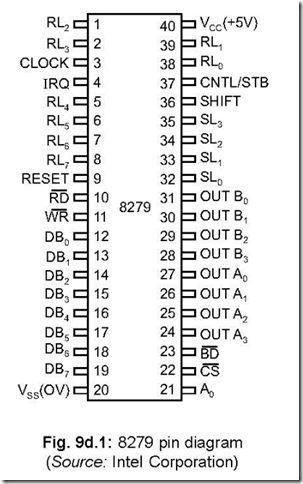
2. Why stack is used in a program?

Ans. The stack is used to store information temporarily during the execution of a program.

Also the stack is used in subroutine calls to store the return address.

As an example, data generated at a certain point in a program may be needed later

in the program. This data is stored in the stack and retrieved when needed. Because the

number of general purpose registers (GPRs) in a microprocessor is limited–hence not all

the temporary data can be stored in them and this is where the stack plays its part.

3. How the stack is initialised?

Ans. The stack is initialised by a 16-bit register, called the stack pointer (SP) register.

4. Is initialisation of stack a must in a program?

Ans. No, it is not a must. If for programs for which any temporary data that are generated can be stored in GPRs and which don’t require subroutine calls, there is no need to initialise the stack by the SP.

5. What the SP register does in a program?

Ans. The SP register keeps a track with regard to the storage and retrieval of data/information.

6. Who uses the stack?

Ans. The stack is used by both the programmer and the system.

Programmer uses the stack for storage/retrieval of data by using the PUSH/POP instructions respectively.

On the other hand, the system uses the stack to store return address whenever subroutine CALL is used.

7. Comment on the size of the stack.

Ans. It depends on the size of the R/W memory, as well as the program length. Since for a given system, the size of the R/W memory is fixed, thus smaller the size of the program, more would be the size of the stack.

8. Where, in the R/W memory, a programmer should initialise the stack?

Ans. The stack should be initialised at the high end of the memory map. This is explained in Fig. 6.1.


10-22-2014 5-27-21 PM

The user program should start at the low end of the memory map, while the stack should be initialised at the high end of the memory map. When the program is being executed, the PC is auto-incremented while as temporary data are stored in the stack, it is auto-decremented. Thus if sufficient gap is not maintained, the program area may get corrupted by the filling-in of the stack. In such a case, the program will ‘crash’.

9. What type of memory is the stack?

Ans. Stack is a ‘last-in first-out’ or LIFO type of memory. This means that data which is pushed last into stack is popped out of it first.
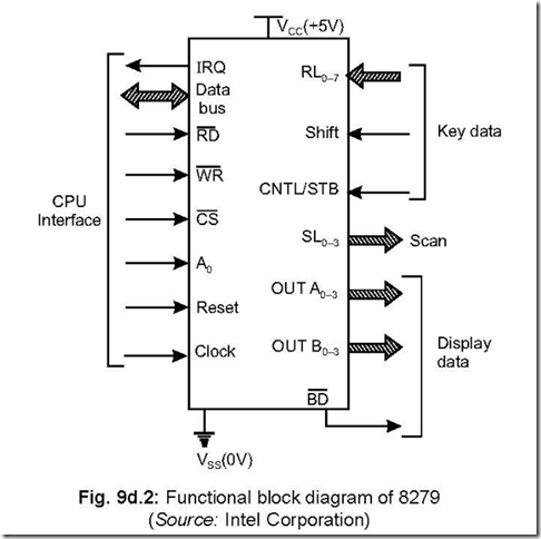
10. How the stack is initialised?

Ans. The stack is initialised by means of the stack pointer. The software instruction is like this: LXI SP, 0044.

It means that the stack is initiated at the memory location 4400 by the stack pointer.

11. What are the software instructions related to stack operations? Ans. The following are stack related software instructions:

LXI SP, address

PUSH rp, POP rp

PUSH PSW, POP PSW

XTHL, SPHL

CALL – RET

DAD SP

12. Does the stack have a fixed address?

Ans. No, the stack does not have a fixed address. But usually it is initialised at the top end of the memory address.

13. What are the typical errors associated with using stack in a program?

Ans. The possible errors in stack usage are: overflow or underflow of stack, PUSH or POP instructions not carried out in proper sequence, etc.

14. By how may memory locations SP is decremented/incremented when PUSH/ POP instruction is performed.

Ans. SP is decremented/incremented by two memory locations when PUSH/POP is executed.

15. What is a subroutine?

Ans. A subroutine is a group of instructions, written separately from the main program, which performs a function that is required repeatedly in the main program.

16. Why a subroutine is used in a program?

Ans. Since a subroutine is called more than once by the main program, thus, use of subroutines saves precious memory space. The more the number of times a subroutine is called by the main program, the more is the saving of memory space.

17. Give some examples of subroutines.

Ans. Some examples of subroutines called by main program are: multiplication program, time delay subroutine, hexa-decimal converter subroutine, display subroutine, apart from any user specific subroutines that may be needed by a programmer.

18. Where do subroutines reside?

Ans. Standard subroutines like display program, time delay program, hexa-decimal conversion

programs are supplied by the manufacturers of microcomputer in monitor ROM, while any user specific programs are written in the R/W memory.
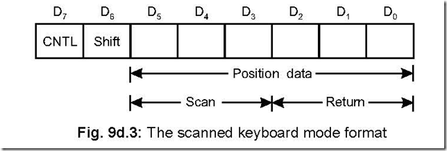
19. How subroutines can be called from the main program?

Ans. Subroutines can be called from the main program either conditionally or unconditionally.

Mnemonic for unconditional call is CALL, while there are eight conditional calls.

These are: CC, CNC, CZ, CNZ, CP, CM, CPE and CPO. CC stands for calling the subroutine if carry flag is set. CPE stands for calling the subroutine if parity flag is set (i.e., even parity).

20. How the program returns from the subroutine?

Ans. The return from the subroutine can be: conditional, unconditional.

The mnemonic for unconditional return is RET, while there are eight conditional

return instructions viz. RC, RNC, RZ, RNZ, RP, RM, RPE and RPO. RZ stands for return

if zero flag is set. RPO stands for return if parity flag is reset (odd parity).

21. Byte wise what are the lengths of CALL and RET instructions? Ans. CALL is a 3-byte instruction, while RET is a 1-byte one.

22. Explain the CALL instruction.

Ans. CALL is a 3-byte unconditional instruction, upon the execution of which the main program branches to the starting address of the subroutine. The CALL instruction looks like this.

CALL memory address

(16-bit)

An example will clarify the situation.

The main program begins at 4080 by initialising the stack pointer at 621F. When

CALL 4400 is encountered at 4100 in the main program, the return address following the CALL is 4103. The program counter is stored with the first address of the subroutine. Thus PC = 4400 and the content of the stack will look like as shown with the upper byte

of the return address i.e., 41 stored at 621E and the lower byte (i.e., 03) at the stack address 621D. Thus, the program now starts at the subroutine starting address 4400.]

10-22-2014 5-27-47 PMWhen the last subroutine instruction RET is encountered, the two contents at the memory locations 621D and 621E are popped out so that the PC content now becomes 4103—which is the return address from the subroutine. Thus the program starts at 4103 in the main program and SP returns to 621F.

23. What is multiple calling of a subroutine?

Ans.

10-22-2014 5-28-17 PM

Subroutines are normally called more than once by the main program. Calling a subroutine more than once by the main program is called “multiple calling of a subroutine.” This is shown in Fig. 6.3.

24. What is meant by ‘parameter passing’?

Ans. Subroutines are scattered at many places in the memory and that they may be called from different locations in the main program. In such cases, various types of information/data are exchanged between the main program and the subroutine. This technique goes by the name “parameter passing”.

25. Name the different types of subroutines. Ans. The different types of subroutines are:

z multiple-calling of a subroutine

z nesting of subroutines

z multiple ending subroutines.

26. Explain nesting of subroutines.

Ans. The process of a subroutine calling a second subroutine and the second subroutine in its turn calling a third one and so on is called nesting of subroutines.

Theoretically speaking, the number of subroutines that can be called by this process

is infinite but, in practice it is limited by the size of memory.
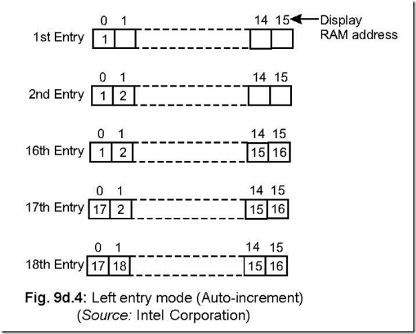
 

10-22-2014 5-29-12 PM


In Fig. 6.4, the main program calls the SR-I, SR-I in its turn calls SR-II while SR-II calls SR-III. The execution of the program is shown by the arrow heads. It is to be noted that each time a subroutine is called, the return addresses are saved automatically in the stack.

27. Draw an example of a multiple ending subroutine and explain.

Ans. The example of a multiple ending subroutine is shown in Fig. 6.5 which shows that the main program calls the subroutine starting at 5500.

Now the return from the subroutine can be via paths (1) or (2) (both conditional) or

(3) (unconditional). Thus the return from the subroutine can be effected in three ways—


10-22-2014 5-29-35 PM

i.e., why it is called a multiple ending subroutine.

28. What are the techniques of ending a subroutine?

Ans. There are two methods of ending a subroutine—multiple ending and common ending. The example of each type follows:

10-22-2014 5-29-54 PM

29. For a 8085 based system, let the following two instructions are carried out

LXI SP, 0000 H

PUSH D

with D = 09 H and E = FA H assumed.

Show the stack contents after PUSH operation.

Ans. Stack gets decremented by one memory location from the one pointed to by the stack pointer. Since the pointer is at 0000 H, so on decrementing, SP now become FFFF H at which the content of D (i.e., 09 H) is stored. The SP is again decremented to become FFFE H where content of E (i.e., FA H) is stored.

10-22-2014 5-49-52 PM

30.Discuss recursive subroutine.

Ans. A recursive subroutine is a subroutine which is called by itself and are used with complex data structures, known as ‘trees’.

For the flow diagram shown, if the subroutine is called with n = 4 (known as ‘recursive depth’), then until n becomes 0 it will stay within the recursive subroutine.

Below is shown the flow diagram for a recursive subroutine.


10-22-2014 5-50-18 PM

31. In how many ways nested subroutines can be classified? Ans. Nested subroutines can be classified in two ways as:

• t subroutine

• e subroutine

32. Discuss re-entrant subroutine.

Ans. In nested subroutines, many subroutines are there. In such a case, if a latter subroutine calls an earlier one, then it is known as re-entrant subroutine.

As an example, say a main program has two subroutines. The main program calls subroutine 1, then subroutine 1 calls subroutine 2. If now subroutine 1 is called from subroutine 2, then this falls under the category of re-entrant subroutines.

A scheme for such re-entrant subroutine is shown below:


10-22-2014 5-50-37 PM


33. How the stack is initialised?

Ans. There are two ways to initialise the stack

(a) Direct way

(b) Indirect way

Example of method (a) is LXI SP, 4400 H which loads the stack pointer with 4400 H. so that it points at the memory address 4400 H.

Example of method (b) is

LXI H, 16-bit data fi load 16-bit data into HL register pair SPHL fi contents of HL register pair is loaded into SP.

In most of the cases the stack pointer is initialised by direct way, but method (b) is sometimes used when one wants to set the stack pointer by means of programming.

34. At what highest memory location can the SP be initialised.

Ans. The stack pointer is decremented by one memory location before data starts storing into the stack.

Hence, theoretically, the stack pointer can be initialised to a value which is one higher them the highest read/write memory location that is available.

35. Exchange the contents of DE register pair with that of HL register pair, using PUSH, POP instructions.

Ans. It is assumed that data are existing in the four registers—D, E, H and L. The following program then interchanges the contents of DE with that of HL and the stack is already initialised by the stack pointer.

PUSH D PUSH H POP D POP H

36. Write a program which will store the contents of accumulator and flag register

at 2000 H and 2001 H memory locations respectively.
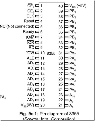
Ans. The following is the program for the above, using PUSH-POP instructions.

LXISP, 4000 H: Stack pointer is initialized at 4000 H.

PUSH PSW: Accumulator and flag register contents pushed into stack

POP B: Accumulator content goes to B and flag register content goes to C register.

MOV A, B: Content of B taken to accumulator.

STA 2000 H: Accumulator content stored into memory location 2000 H. MOV A, C : Content of C moved to accumulator.

STA 2001 H: Accumulator content stored into memory location 2001 H HLT: Program halted.

37. What is meant by ‘parameter passing technique’ as used in subroutines?

Ans. Subroutines are programs, written separately from the main program, to process data or address variable that occurs repeatedly in the main program.

In order that the subroutine can process data, it is necessary to pass the data/address variable to the subroutine. This ‘passing’ of data/address variable is referred to as passing parameters to the subroutine.

There are four ways in which this ‘passing’ can be done, as mentioned below:

(a) by using registers

(b) by using pointers

(c) by using memory

(d) by using stack.