Advanced PIC18 Projects—SD Card Projects:Using the Card Filing System

PROJECT 7.3—Using the Card Filing System

The hardware of this project is the same as for Project 7.1 (i.e., as shown in Figure 7.8).

In this project, a file called MYFILE55.TXT is created on the SD card. String “This is MYFILE.TXT” is written to the file initially. Then the string “This is the added data.. .” is appended to the file. The program then reads the contents of the file and sends the string “This is MYFILE.TXT. This is the added data.. .” to the UART, enabling the data to be displayed on the PC screen when HyperTerminal is run.

Advanced PIC18 Projects—SD Card Projects-0113

Advanced PIC18 Projects—SD Card Projects-0114

The program listing of the project is given in Figure 7.12 (program SD3.C).

At the beginning of the program the UART is initialized to 2400 baud. Then the SPI bus and the FAT file system are initialized as required by the library.

The program then creates file MYFILE55.TXT by calling library function Mmc_Fat_Assign with the arguments as the filename and the creation flag 0x80, which tells the function to create a new file if the file does not exist. The filename should be in “filename.extension” format, though it is also possible to specify an eight-digit filename and a three-digit extension with no “.” between them, as the “.” will be inserted by the function. Other allowed values of the creation flag are given in Table 7.8. Note that the SD card must have been formatted in FAT16 before we can read or write to it. Most new cards are already formatted, but we can also use the Mmc_Fat_QuickFormat function to format a card.

The file is cleared (if it is not already empty) using function call Mmc_Fat_Rewrite, and then the string “This is MYFILE.TXT” is written to the file by calling library function Mmc_Fat_Write. Note that the size of the data to be written must be specified as the second argument of this function call. Then Mmc_Fat_Append is called and the second string “This is the added data.. .” is appended to the file.

Calling function Mmc_Fat_Reset sets the file pointer to the beginning of the file and also returns the size of the file. Finally, a for loop is set up to read each character from the file using the Mmc_Fat_Read function call, and the characters read are sent to the UART with the Usart_Write function call.

Advanced PIC18 Projects—SD Card Projects-0115

Advanced PIC18 Projects—SD Card Projects-0116Advanced PIC18 Projects—SD Card Projects-0117


Advanced PIC18 Projects—CAN Bus Projects:PIC18F258 Microcontroller

PIC18F258 Microcontroller

Later in this chapter the PIC18F258 microcontroller is used in a CAN bus–based project. This section describes this microcontroller and its operating principles with respect to its built-in CAN bus. The principles here are in general applicable to other PIC microcontrollers with CAN modules.

The PIC18F258 is a high performance 8-bit microcontroller with integrated CAN module. The device has the following features:

• 32K flash program memory

• 1536 bytes RAM data memory

• 256 bytes EEPROM memory

• 22 I/O ports

• 5-channel 10-bit A/D converters

• Three timers/counters

• Three external interrupt pins

• High-current (25mA) sink/source

• Capture/compare/PWM module

• SPI/I2C module

• CAN 2.0A/B module

• Power-on reset and power-on timer

• Watchdog timer

• Priority level interrupts

• DC to 40MHz clock input

• 8 x 8 hardware multiplier

• Wide operating voltage (2.0V to 5.5V)

• Power-saving sleep mode

The features of the PIC18F258 microcontroller’s CAN module are as follows:

• Compatible with CAN 1.2, CAN 2.0A, and CAN 2.0B

• Supports standard and extended data frames

• Programmable bit rate up to 1Mbit/s

• Double-buffered receiver

• Three transmit buffers

• Two receive buffers

• Programmable clock source

• Six acceptance filters

• Two acceptance filter masks

• Loop-back mode for self-testing

• Low-power sleep mode

• Interrupt capabilities

The CAN module uses port pins RB3/CANRX and RB2/CANTX for CAN bus receive and transmit functions respectively. These pins are connected to the CAN bus via an MCP2551-type CAN bus transceiver chip.

The PIC18F258 microcontroller supports the following frame types:

• Standard data frame

• Extended data frame

• Remote frame

• Error frame

• Overload frame

• Interframe space

A node uses filters to decide whether or not to accept a received message. Message filtering is applied to the whole identifier field, and mask registers are used to specify which bits in the identifier the filters should examine.

The CAN module in the PIC18F258 microcontroller has six modes of operation:

• Configuration mode

• Disable mode

• Normal operation mode

• Listen-only mode

• Loop-back mode

• Error recognition mode

Configuration Mode

The CAN module is initialized in configuration mode. The module is not allowed to enter configuration mode while a transmission is taking place. In configuration mode the module will neither transmit nor receive, the error counters are cleared, and the interrupt flags remain unchanged.

Disable Mode

In disable mode, the module will neither transmit nor receive. In this mode the internal clock is stopped unless the module is active. If the module is active, it will wait for 11 recessive bits on the CAN bus, detect that condition as an IDLE bus, and then accept the module disable command. The WAKIF interrupt (wake-up interrupt) is the only CAN module interrupt that is active in disable mode.

Normal Operation Mode

The normal operation mode is the CAN module’s standard operating mode. In this mode, the module monitors all bus messages and generates acknowledge bits, error frames, etc. This is the only mode that can transmit messages.

Listen-only Mode

The listen-only mode allows the CAN module to receive messages, including messages with errors. It can be used to monitor bus activities or to detect the baud rate on the bus. For automatic baud rate detection, at least two other nodes must be communicating with each other. The baud rate can be determined by testing different values until valid messages are received. The listen-only mode cannot transmit messages.

Loop-Back Mode

In the loop-back mode, messages can be directed from internal transmit buffers to receive buffers without actually transmitting messages on the CAN bus. This mode is useful during system developing and testing.

Error Recognition Mode

The error recognition mode is used to ignore all errors and receive all messages. In this mode, all messages, valid or invalid are received and copied to the receive buffer.

CAN Message Transmission

The PIC18F258 microcontroller implements three dedicated transmit buffers: TXB0, TXB1, and TXB2. Pending transmittable messages are in a priority queue. Before the SOF is sent, the priorities of all buffers queued for transmission are compared. The transmit buffer with the highest priority is sent first. If two buffers have the same priority, the one with the higher buffer number is sent first. There are four levels of priority.

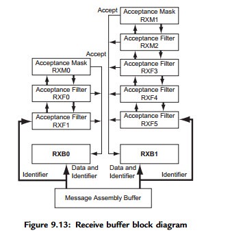
CAN Message Reception

Reception of a message is a more complex process. The PIC18F258 microcontroller includes two receive buffers, RXB0 and RXB1, with multiple acceptance filters

for each (see Figure 9.13). All received messages are assembled in the message assembly buffer (MAB). Once a message is received, regardless of the type of identifier and the number of data bytes, the entire message is copied into the MAB.

Received messages have priorities. RXB0 is the higher priority buffer, and it has two message acceptance filters, RXF0 and RXF1. RXB1 is the lower priority buffer and has four acceptance filters: RXF2, RXF3, RXF4, and RXF5. Two programmable acceptance filter masks, RXM0 and RXM1, are also available, one for each receive buffer.

Advanced PIC18 Projects—CAN Bus Projects -0205

The CAN module uses message acceptance filters and masks to determine if a message in the MAB should be loaded into a receive buffer. Once a valid message is received by the MAB, the identifier field of the message is compared to the filter values. If there is a match, that message is loaded into the appropriate receive buffer. The filter masks determine which bits in the identifier are examined with the filters. The truth table in Table 9.3 shows how each bit in the identifier is compared against

Advanced PIC18 Projects—CAN Bus Projects -0206

the masks and filters to determine if the message should be accepted. If a mask bit is set to 0, that bit in the identifier is automatically accepted regardless of the filter bit.

Calculating the Timing Parameters

Setting the nodes’ timing parameters is essential for the bus to operate reliably. Given the microcontroller clock frequency and the required CAN bus bit rate, we can calculate the values of the following timing parameters:

• Baud rate prescaler value

• Prop_Seg value

• Phase_Seg1 value

• Phase_Seg2 value

• SJW value

Correct timing requires that

• Prop_Seg þ Phase_Seg1 ::: Phase_Seg2

• Phase_Seg2 ::: SJW

The following example illustrates the calculation of these timing parameters.

Example 9.2

Assuming the microcontroller oscillator clock rate is 20MHz and the required CAN bit rate is 125KHz, calculate the timing parameters.

Solution 9.2

With a 20MHz clock rate, the clock period is 50ns. Choosing a baud rate prescaler value of 4, from Equation (9.4), TQ ¼ 2 * (BRP þ 1) * TOSC, gives a time quantum of TQ ¼ 500ns. To obtain a nominal bit rate of 125KHz, the nominal bit time must be:

TBIT ¼ 1=0:125MHz ¼ 8ms; or 16TQ

The Sync_Segment is 1TQ. Choosing 2TQ for the Prop_Seg, and 7TQ for Phase_Seg1 leaves 6TQ for Phase_Seg2 and places the sampling point at 10TQ at the end of Phase_Seg1.

By the rules described earlier, the SJW can be the maximum allowed (i.e., 4). However, a large SJW is only necessary when the clock generation of different nodes is not stable or accurate (e.g., if ceramic resonators are used). Typically, a SJW of 1 is enough. In summary, the required timing parameters are:

Advanced PIC18 Projects—CAN Bus Projects -0207

The sampling point is at 10TQ which corresponds to 62.5% of the total bit time.

There are several tools available for free on the Internet for calculating CAN bus timing parameters. One such tool is the CAN Baud Rate Calculator, developed by Artic Consultants Ltd (http://www.articconsultants.co.uk). An example using this tool follows.

Example 9.3

Assuming the microcontroller oscillator clock rate is 20MHz and the required CAN bit rate is 125KHz, calculate the timing parameters using the CAN Baud Rate Calculator.

Solution 9.3

Figure 9.14 shows the output of the CAN Baud Rate Calculator program. The device type is selected as PIC18Fxxx8, the oscillator frequency is entered as 20MHz, and the CAN bus baud rate is entered as 125KHz.

Clicking the Calculate Settings button calculates and displays the recommended timing parameters. In general, there is more than one solution, and different solutions are given in the Calculated Solutions field’s drop-down menu.

In choosing Solution 2 from the drop-down menu, the following timing parameters are recommended by the program:

Advanced PIC18 Projects—CAN Bus Projects -0208


Simple PIC18 Projects

In this chapter we will look at the design of simple PIC18 microcontroller-based projects, with the idea of becoming familiar with basic interfacing techniques and learning how to use the various microcontroller peripheral registers. We will look at the design of projects using LEDs, push-button switches, keyboards, LED arrays, sound devices, and so on, and we will develop programs in C language using the mikroC compiler. The hardware is designed on a low-cost breadboard, but development kits such as BIGPIC4 can be used for these projects. We will start with very simple projects and proceed to more complex ones. It is recommended that the reader moves through the projects in their given order. The following are provided for each project:

• Description of the program

• Description of the hardware

• Circuit diagram

• Algorithm description (in PDL)

• Program listing

• Suggestions for further development

The program’s algorithm can be described in a variety of graphic and text-based methods, some of the common ones being a flow diagram, a structure chart, and program description language. In this book we are using program description language (PDL).


Multi-Tasking and Real-Time Operating Systems:Voltmeter with RS232 Serial Output

PROJECT 10.3—Voltmeter with RS232 Serial Output

In this RTOS project, which is more complex than the preceding ones, the voltage is read using an A/D converter and then sent over the serial port to a PC. The project consists of three tasks: Live, Get_voltage, and To_RS232.

• Task Live runs every 200ms and flashes an LED connected to port RD7 of the microcontroller to indicate that the system is working.

• Task Get_voltage reads channel 0 of the A/D converter where the voltage to be measured is connected. The read value is formatted and then stored in a variable. This task runs every two seconds.

• Task To_RS232 reads the formatted voltage and sends it over the RS232 line to a PC every second.

Figure 10.12 shows the block diagram of the project. The circuit diagram is given in Figure 10.13. A PIC18F8520-type microcontroller with a 10MHz crystal is used in this project (though any PIC18F-series microcontroller can be used). The voltage to be measured is connected to analog port AN0 of the microcontroller. The RS232 TX output of the microcontroller (RC6) is connected to a MAX232-type RS232-level converter chip and then to the serial input of a PC (e.g., COM1) using a 9-pin D-type connector. Port pin RD7 is connected to an LED to indicate whether the project is working.

Multi-Tasking and Real-Time Operating Systems-0236

The program listing (RTOS3.C) of the project is given in Figure 10.14. At the beginning of the program, the A/D is defined as 10 bits, the clock is defined as 10MHz, and the RS232 speed is defined as 2400 baud. The RTOS timer and the minor_cycle are then defined using the #use rtos preprocessor command.

Multi-Tasking and Real-Time Operating Systems-0237

In the main part of the program PORTD is configured as output and all PORTD pins are cleared. Then PORTA is configured as input (RA0 is the analog input), the microcontroller’s analog inputs are configured, the A/D clock is set, and the A/D channel 0 is selected (AN0). The RTOS is then started by calling function rtos_run().

The program consists of three tasks:

• Task Live runs every 200ms and flashes an LED connected to port pin RD7 of the microcontroller to indicate that the project is working.

• Task Get_voltage reads the analog voltage from channel 0 (pin RA0 or AN0) of the microcontroller. The value is then converted into millivolts by multiplying by 5000 and dividing by 1024 (in a 10-bit A/D there are 1024 quantization levels, and when working with a reference voltage of þ5V, each quantization level corresponds to 5000/1024mV). The voltage is stored in a global variable called Volts.

Multi-Tasking and Real-Time Operating Systems-0238

Multi-Tasking and Real-Time Operating Systems-0239

• Task To_RS232 reads the measured voltage from common variable Volts and sends it to the RS232 port using the C printf statement. The result is sent in the following format:

Measured voltage ¼ nnnn mV

The HyperTerminal program is run on the PC to get an output from the program. A typical screen output is shown in Figure 10.15.

Multi-Tasking and Real-Time Operating Systems-0240

Using a Semaphore

The program given in Figure 10.14 is working and displays the measured voltage on the PC screen. This program can be improved slightly by using a semaphore to

synchronize the display of the measured voltage with the A/D samples. The modified

Multi-Tasking and Real-Time Operating Systems-0241

Multi-Tasking and Real-Time Operating Systems-0242

program (RTOS4.C) is given in Figure 10.16. The operation of the new program is as follows:

• The semaphore variable (sem) is set to 1 at the beginning of the program.

• Task Get_voltage decrements the semaphore (calls rtos_wait) variable so that task To_RS232 is blocked (semaphore variable sem ¼ 0) and cannot

send data to the PC. When a new A/D sample is ready, the semaphore variable is incremented (calls rtos_signal) and task To_RS232 can continue. Task To_RS232 then sends the measured voltage to the PC and increments the semaphore variable to indicate that it had access to the data. Task Get_voltage can then get a new sample. This process is repeated forever.


Multi-Tasking and Real-Time Operating Systems:Random Number Generator

PROJECT 10.2—Random Number Generator

In this slightly more complex RTOS project, a random number between 0 and 255 is generated. Eight LEDs are connected to PORTB of a PIC18F452 microcontroller. In addition, a push-button switch is connected to bit 0 of PORTD (RD0), and an LED is connected to bit 7 of PORTD (RD7).

Three tasks are used in this project: Live, Generator, and Display.

• Task Live runs every 200ms and flashes the LED on port pin RD7 to indicate that the system is working.

• Task Generator increments a variable from 0 to 255 continuously and checks the status of the push-button switch. When the push-button switch is pressed, the value of the current count is sent to task Display using a messaging queue.

• Task Display reads the number from the message queue and sends the received byte to the LEDs connected to PORTB. Thus, the LEDs display a random pattern every time the push button is pressed.

Figure 10.9 shows the project’s block diagram. The circuit diagram is given in Figure 10.10. The microcontroller is operated from a 4MHz crystal.

Multi-Tasking and Real-Time Operating Systems-0232

Multi-Tasking and Real-Time Operating Systems-0233

The program listing of the project (RTOS2.C) is given in Figure 10.11. The main part of the program is in the later portion, and it configures PORTB pins as outputs. Also,

bit 0 of PORTD is configured as input and other pins of PORTD are configured as outputs.

Timer 0 is used as the RTOS timer, and the minor_cycle is set to 1s. The program consists of three tasks:

• Task Live runs every 200ms and flashes the LED connected to port pin RD7.

This LED indicates that the system is working.

• Task Generator runs every millisecond and increments a byte variable called count continuously. When the push-button switch is pressed, pin 0 of PORTD (RD0) goes to logic 0. When this happens, the current value of count is sent to task Display using RTOS function call rtos_msg_send(display, count), where

Multi-Tasking and Real-Time Operating Systems-0234

Multi-Tasking and Real-Time Operating Systems-0235

Display is the name of the task where the message is sent and count is the byte sent.

• Task Display runs every 10ms. This task checks whether there is a message in the queue. If so, the message is extracted using RTOS function call rtos_msg_read(), and the read byte is sent to the LEDs connected to PORTB.

Thus, the LEDs display the binary value of count as the switch is pressed. The message queue should be checked by using function rtos_msg_poll(), as trying to read the queue without any bytes in the queue may freeze the program.


Multi-Tasking and Real-Time Operating Systems:CCS PIC C Compiler RTOS

CCS PIC C Compiler RTOS

The CCS PIC C compiler is one of the popular C compilers for the PIC16 and PIC18 series of microcontrollers. In addition to their PIC compilers, Customer Computer Services offers PIC in-circuit emulators, simulators, microcontroller programmers, and various development kits. The syntax of the CCS C language is slightly different from that of the mikroC language, but readers who are familiar with mikroC should find CCS C easy to use.

CCS C supports a rudimentary multi-tasking cooperative RTOS for the PIC18 series of microcontrollers that uses their PCW and PCWH compilers. This RTOS allows a PIC microcontroller to run tasks without using interrupts. When a task is scheduled to run, control of the processor is given to that task. When the task is complete or does not need the processor any more, control returns to a dispatch function, which gives control of the processor to the next scheduled task. Because the RTOS does not use interrupts and is not preemptive, the user must make sure that a task does not run forever.

Further details about the RTOS are available in the compiler’s user manual.

The CCS language provides the following RTOS functions in addition to the normal C functions:

rtos_run() initiates the operation of RTOS. All task control operations are implemented after calling this function.

rtos_terminate() terminates the operation of RTOS. Control returns to the original program without RTOS. In fact, this function is like a return from rtos_run().

rtos_enable() receives the name of a task as an argument. The function enables the task so function rtos_run() can call the task when its time is due.

rtos_disable() receives the name of a task as an argument. The function disables the task so it can no longer be called by rtos_run() unless it is re-enabled by calling rtos_enable().

rtos_ yield(), when called from within a task, returns control to the dispatcher. All tasks should call this function to release the processor so other tasks can utilize the processor time.

rtos_msg_send() receives a task name and a byte as arguments. The function sends the byte to the specified task, where it is placed in the task’s message queue.

rtos_msg_read() reads the byte located in the task’s message queue.

rtos_msg_ poll() returns true if there is data in the task’s message queue. This function should be called before reading a byte from the task’s message queue.

rtos_signal() receives a semaphore name and increments that semaphore.

rtos_wait() receives a semaphore name and waits for the resource associated with the semaphore to become available. The semaphore count is then decremented so the task can claim the resource.

rtos_await() receives an expression as an argument, and the task waits until the expression evaluates to true.

rtos_overrun() receives a task name as an argument, and the function returns true if that task has overrun its allocated time.

rtos_stats() returns the specified statistics about a specified task. The statistics can be the minimum and maximum task run times and the total task run time. The task name and the type of statistics are specified as arguments to the function.

Preparing for RTOS

In addition to the preceding functions, the #use rtos() preprocessor command must be specified at the beginning of the program before calling any of the RTOS functions. The format of this preprocessor command is:

Multi-Tasking and Real-Time Operating Systems-0227

where timer is between 0 and 4 and specifies the processor timer that will be used by the RTOS, and minor_cycle is the longest time any task will run. The number entered here must be followed by s, ms, us, or ns.

In addition, a statistics option can be specified after the minor_cycle option, in which case the compiler will keep track of the minimum and maximum processor times the task uses at each call and the task’s total time used.

Declaring a Task

A task is declared just like any other C function, but tasks in a multi-tasking application do not have any arguments and do not return any values. Before a task is declared, a

#task preprocessor command is needed to specify the task options. The format of this preprocessor command is:

#task(rate¼n, max¼m, queue¼p)

where rate specifies how often the task should be called. The number specified must be followed by s, ms, us, or ns. max specifies how much processor time a task will use in one execution of the task. The time specifed here must be equal to or less than the time specified by minor_cycle. queue is optional and if present specifies the number of bytes to be reserved for the task to receive messages from other tasks.

The default value is 0.

In the following example, a task called my_ticks is every 20ms and is expected to use no more than 100ms of processor time. This task is specified with no queue option:

Multi-Tasking and Real-Time Operating Systems-0228


Multi-Tasking and Real-Time Operating Systems:LEDs

PROJECT 10.1—LEDs

In the following simple RTOS-based project, four LEDs are connected to the lower half of PORTB of a PIC18F452-type microcontroller. The software consists of four tasks, where each task flashes an LED at a different rate:

• Task 1, called task_B0, flashes the LED connected to port RB0 at a rate of 250ms.

• Task 2, called task_B1, flashes the LED connected to port RB1 at a rate of 500ms.

• Task 3, called task_B2, flashes the LED connected to port RB2 once a second.

• Task 4, called task_B3, flashes the LED connected to port RB3 once every two seconds.

Figure 10.7 shows the circuit diagram of the project. A 4MHz crystal is used as the clock. PORTB pins RB0–RB3 are connected to the LEDs through current limiting resistors.

Multi-Tasking and Real-Time Operating Systems-0229

The software is based on the CCS C compiler, and the program listing (RTOS1.C) is given in Figure 10.8. The main program is at the end of the program, and inside the main program PORTB pins are declared as outputs and RTOS is started by calling function rtos_run().

The file that contains CCS RTOS declarations should be included at the beginning of the program. The preprocessor command #use delay tells the compiler that we are using

Multi-Tasking and Real-Time Operating Systems-0230

Multi-Tasking and Real-Time Operating Systems-0231

a 4MHz clock. Then the RTOS timer is declared as Timer 0, and minor_cycle time is declared as 10ms using the preprocessor command #use rtos.

The program consists of four similar tasks:

• task_B0 flashes the LED connected to RB0 at a rate of 250ms. Thus, the LED is ON for 250ms, then OFF for 250ms, and so on. CCS statement output_toggle is used to change the state of the LED every time the task is called. In the CCS compiler PIN_B0 refers to port pin RB0 of the microcontroller.

• task_B1 flashes the LED connected to RB1 at a rate of 500ms as described.

• task_B2 flashes the LED connected to RB2 every second as described.

• Finally, task_B3 flashes the LED connected to RB3 every two seconds as described.

The program given in Figure 10.8 is a multi-tasking program where the LEDs flash independently of each other and concurrently.


Multi-Tasking and Real-Time Operating Systems:The Real-Time Operating System (RTOS)

The Real-Time Operating System (RTOS)

Real-time operating systems are built around a multi-tasking kernel which controls the allocation of time slices to tasks. A time slice is the period of time a given task has for execution before it is stopped and replaced by another task. This process, also known as context switching, repeats continuously. When context switching occurs, the executing task is stopped, the processor registers are saved in memory, the processor registers of the next available task are loaded into the CPU, and the new task begins execution. An RTOS also provides task-to-task message passing, synchronization of tasks, and allocation of shared resources to tasks.

The basic parts of an RTOS are:

• Scheduler

• RTOS services

• Synchronization and messaging tools

The Scheduler

A scheduler is at the heart of every RTOS, as it provides the algorithms to select the tasks for execution. Three of the more common scheduling algorithms are:

• Cooperative scheduling

• Round-robin scheduling

• Preemptive scheduling

Cooperative scheduling is perhaps the simplest scheduling algorithm available. Each task runs until it is complete and gives up the CPU voluntarily. Cooperative scheduling cannot satisfy real-time system needs, since it cannot support the prioritization of tasks according to importance. Also, a single task may use the CPU too long, leaving too little time for other tasks. And the scheduler has no control of the various tasks’ execution time. A state machine construct is a simple form of a cooperative scheduling technique.

In round-robin scheduling, each task is assigned an equal share of CPU time (see Figure 10.4). A counter tracks the time slice for each task. When one task’s time slice completes, the counter is cleared and the task is placed at the end of the cycle. Newly added tasks are placed at the end of the cycle with their counters cleared to 0. This, like cooperative scheduling, is not very useful in a real-time system, since very often some tasks take only a few milliseconds while others require hundreds of milliseconds or more.

Multi-Tasking and Real-Time Operating Systems-0224

Preemptive scheduling is considered a real-time scheduling algorithm. It is priority- based, and each task is given a priority (see Figure 10.5). The task with the highest priority gets the CPU time. Real-time systems generally support priority levels ranging from 0 to 255, where 0 is the highest priority and 255 is the lowest.

Multi-Tasking and Real-Time Operating Systems-0225

In some real-time systems where more than one task can be at the same priority level, preemptive scheduling is mixed with round-robin scheduling. In such cases, tasks at higher priority levels run before lower priority ones, and tasks at the same priority level run by round-robin scheduling. If a task is preempted by a higher priority task, its run time counter is saved and then restored when it regains control of the CPU.

In some systems a strict real-time priority class is defined where tasks above this class may run to completion (or run until a resource is not available) even if there are other tasks at the same priority level.

In a real-time system a task can be in any one of the following states (see Figure 10.6):

• Ready to run

• Running

• Blocked

When a task is first created, it is usually ready to run and is entered in the task list. From this state, subject to the scheduling algorithm, the task can become a running task. According to the conditions of preemptive scheduling, the task will run if it is the highest priority task in the system and is not waiting for a resource.

Multi-Tasking and Real-Time Operating Systems-0226

A running task becomes a blocked task if it needs a resource that is not available. For example, a task may need data from an A/D converter and is blocked until it is

available. Once the resource can be accessed, the blocked task becomes a running task if it is the highest priority task in the system, otherwise it moves to the ready state. Only a running task can be blocked. A ready task cannot be blocked.

When a task moves from one state to another, the processor saves the running task’s context in memory, loads the new task’s context from memory, and then executes the new instructions as required.

The kernel usually provides an interface to manipulate task operations. Typical task operations are:

• Creating a task

• Deleting a task

• Changing the priority of a task

• Changing the state of a task

RTOS Services

RTOS services are utilities provided by the kernel that help developers create real-time tasks efficiently. For example, a task can use time services to obtain the current date and time. Some of these services are:

• Interrupt handling services

• Time services

• Device management services

• Memory management services

• Input-output services

Synchronization and Messaging Tools

Synchronization and messaging tools are kernel constructs that help developers create real-time applications. Some of these services are:

• Semaphores

• Event flags

• Mailboxes

• Pipes

• Message queues

Semaphores are used to synchronize access to shared resources, such as common data areas. Event flags are used to synchronize the intertask activities. Mailboxes, pipes, and message queues are used to send messages among tasks.


Multi-Tasking and Real-Time Operating Systems:State Machines

State Machines

State machines are simple constructs used to perform several activities, usually in a sequence. Many real-life systems fall into this category. For example, the operation of a washing machine or a dishwasher is easily described with a state machine construct.

Perhaps the simplest method of implementing a state machine construct in C is to use a switch-case statement. For example, our temperature monitoring system has three tasks, named Task 1, Task 2, and Task 3 as shown in Figure 10.1. The state machine implementation of the three tasks using switch-case statements is shown in Figure 10.2. The starting state is 1, and each task increments the state number by one to select the next state to be executed. The last state selects state 1, and there is a delay at the end of the switch-case statement. The state machine construct is executed continuously inside an endless for loop.

Multi-Tasking and Real-Time Operating Systems-0222

Multi-Tasking and Real-Time Operating Systems-0223

State machines, although easy to implement, are primitive and have limited application. They can only be used in systems which are not truly responsive, where the task activities are well-defined and the tasks are not prioritized.

Moreover, some tasks may be more important than others. We may want some tasks to run whenever they become eligible. For example, in a manufacturing plant, a task that sets off an alarm when the temperature is too hot must be run. This kind of implementation of tasks requires a sophisticated system like RTOS.


Advanced PIC18 Projects—CAN Bus Projects:CAN Bus Programming

CAN Bus Programming

To operate the PIC18F258 microcontroller on the CAN bus, perform the following steps:

• Configure the CAN bus I/O port directions (RB2 and RB3)

• Initialize the CAN module (CANInitialize)

• Set the CAN module to CONFIG mode (CANSetOperationMode)

• Set the mask registers (CANSetMask)

• Set the filter registers (CANSetFilter)

• Set the CAN module to normal mode (CANSetOperationMode)

• Write/read data (CANWrite/CANRead)

PROJECT 9.1—Temperature Sensor CAN Bus Project

The following is a simple two-node CAN bus–based project. The block diagram of the project is shown in Figure 9.15. The system is made up of two CAN nodes. One node (called DISPLAY node) requests the temperature every second and displays it on an LCD. This process is repeated continuously. The other node (called COLLECTOR node) reads the temperature from an external semiconductor temperature sensor.

Advanced PIC18 Projects—CAN Bus Projects -0213

The project’s circuit diagram is given in Figure 9.16. Two CAN nodes are connected together using a two-meter twisted pair cable, terminated with a 120-ohm resistor at each end.

Advanced PIC18 Projects—CAN Bus Projects -0214

The DISPLAY Processor

Like the COLLECTOR processor, the DISPLAY processor consists of a PIC18F258 microcontroller with a built-in CAN module and an MCP2551 transceiver chip. The microcontroller is operated from an 8MHz crystal. The MCLR input is connected to an external reset button. The CAN outputs (RB2/CANTX and RB3/CANRX) of the microcontroller are connected to the TXD and RXD inputs of the MCP2551. Pins CANH and CANL of the transceiver chip are connected to the CAN bus. An HD44780-type LCD is connected to PORTC of the microcontroller to display the temperature values.

The COLLECTOR Processor

The COLLECTOR processor consists of a PIC18F258 microcontroller with a built-in CAN module and an MCP2551 transceiver chip. The microcontroller is

operated from an 8MHz crystal. The MCLR input is connected to an external reset button. Analog input AN0 of the microcontroller is connected to a LM35DZ-type semiconductor temperature sensor. The sensor can measure temperature in the range of 0oC to 100oC and generates an analog voltage directly proportional to the measured temperature (i.e., the output is 10mV/oC). For example, at 20oC the output voltage is 200mV.

The CAN outputs (RB2/CANTX and RB3/CANRX) of the microcontroller are connected to the TXD and RXD inputs of an MCP2551-type CAN transceiver chip. The CANH and CANL outputs of this chip are connected directly to a twisted cable terminating at the CAN bus. The MCP2551 is an 8-pin chip that supports data rates up to 1Mb/s. The chip can drive up to 112 nodes. An external resistor connected to pin 8 of the chip controls the rise and fall times of CANH and CANL so that EMI can be reduced. For high-speed operation this pin should be connected to ground. A reference voltage equal to VDD/2 is output from pin 5 of the chip.

The program listing is in two parts: the DISPLAY program and the COLLECTOR program. The operation of the system is as follows:

• The DISPLAY processor requests the current temperature from the COLLECTOR processor over the CAN bus

• The COLLECTOR processor reads the temperature, formats it, and sends to the DISPLAY processor over the CAN bus

• The DISPLAY processor reads the temperature from the CAN bus and then displays it on the LCD

• This process is repeated every second

DISPLAY Program

Figure 9.17 shows the program listing of the DISPLAY program, called DISPLAY.C. At the beginning of the program PORTC pins are configured as outputs, RB3 is configured as input (CANRX), and RB2 is configured as output (CANTX). In this project the CAN bus bit rate is selected as 100Kb/s. With a microcontroller clock frequency of 8MHz, the Baud Rate Calculator program (see Figure 9.14) is used to calculate the timing parameters as:

The mikroC CAN bus function CANInitialize is used to initialize the CAN module. The timing parameters and the initialization flag are specified as arguments in this function. The initialization flag is made up from the bitwise AND of:

Advanced PIC18 Projects—CAN Bus Projects -0215

Where sampling the bus three times is specified, the standard identifier is specified, double buffering is turned on, and the line filter is turned off.

Then the operation mode is set to CONFIG and the filter masks and filter values are specified. Both mask1 and mask2 are set to all 1’s (-1 is a shorthand way of writing hexadecimal FFFFFFFF, i.e., setting all mask bits to 1’s) so that all filter bits match up with incoming data.

Advanced PIC18 Projects—CAN Bus Projects -0216

Advanced PIC18 Projects—CAN Bus Projects -0217

Advanced PIC18 Projects—CAN Bus Projects -0218

Filter 3 for buffer 2 is set to value 3 so that identifiers having values 3 are accepted by the receive buffer.

The operation mode is then set to NORMAL. The program then configures the LCD and displays the message “CAN BUS” for one second on the LCD.

The main program loop executes continuously and starts with a for statement. Inside this loop the LCD is cleared and text “TEMP ¼” is displayed on the LCD. Then character “T” is sent over the bus with the identifier equal to 500 (the COLLECTOR

Advanced PIC18 Projects—CAN Bus Projects -0219

Advanced PIC18 Projects—CAN Bus Projects -0220

Advanced PIC18 Projects—CAN Bus Projects -0221

node filter is set to accept identifier 500). This is a request to the COLLECTOR node to send the temperature reading. The program then reads the temperature from the CAN bus, converts it to a string in array txt, and displays it on the LCD. This process repeats after a one-second delay.

COLLECTOR Program

Figure 9.18 shows the program listing of the COLLECTOR program, called COLLECTOR.C. The initial part of this program is the same as the DISPLAY program. The receive filter is set to 500 so that messages with identifier 500 are accepted by the program.

Inside the program loop, the program waits until it receives a request to send the temperature. Here the request is identified by the reception of character “T”. Once a valid request is received, the temperature is read and converted into oC (stored in variable temperature) and then sent to the CAN bus as a byte with an identifier value equal to 3. This process repeats forever.