10.6.1 Program Control Instructions
These instructions include branches, jumps, and subroutine calls as listed in Table 10.11.
Consider Bee d. There are 14 branch conditions. This means that the cc in Bee can be replaced by 14 conditions providing 14 instructions: BCC, BCS, BEQ, BGE, BGT, BHI, BLE, BLS, BLT, BMI, BNE, BPL, BVC, and BVS. It should be mentioned that some of these instructions are applicable to both signed and unsigned numbers, some can be used with only signed numbers, and some instructions are applicable to only unsigned numbers.
After signed arithmetic operations, instructions such as BEQ, BNE, BVS, BVC, BMI, and BPL can be used. On the other hand, after unsigned arithmetic operations, instructions such as BCC, BCS, BEQ, and BNE can be used. It should be pointed out that if V = 0, BPL and BGE have the same meaning, Likewise, if V = 0, BMI and BLT perform the same function.
The conditional branch instruction can be used after typical arithmetic instructions such as subtraction to branch to a location if cc is true. For example, consider SUB. W 01, 02. Now if [D1] and [D2] are unsigned numbers, then
Now as a specific example, consider BEQ BEGIN. If current [PC] = 000200 16, and BEGIN=$20 then, after execution of this BEQ, program execution starts at 000220 16 if Z = I; if Z = 0, program execution continues at 000200 16• The instructions BRA and JMP are unconditional jump instructions. BRA uses the relative addressing mode, whereas JMP uses only control addressing mode. For example, consider BRA.B START. If [PC]= 000200 16, and START=$40 then, after execution of this BRA, program execution starts at 000240 16• Now, consider JMP (Al) . If [Al] = 00000220 16, then, after execution of this JMP, program execution starts at 000220 16•
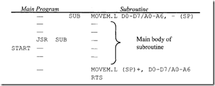
• The instructions BSR and JSR are subroutine call instructions. BSR uses the relative mode, whereas JSR uses the control addressing mode. Consider the following program segment: Assume that the main program uses all registers; the subroutine stores the result in memory.
Here, the JSR SUB instruction calls the subroutine SUB. In response to JSR, the 68000 pushes the current PC contents called START onto the stack and loads the starting address SUB of the subroutine into PC. The first MOVEM in the SUB pushes all registers onto the stack and, after the subroutine is executed, the second MOVEM instruction pops all the registers back. Finally, RTS pops the address START from the stack into PC, and program control in returned to the main program. Note that BSR SUB could have been used instead of JSR SUB in the main program. In that case, the 68000 assembler would have considered the SUB with BSR as a displacement rather than as an address with the JSR instruction.
• DBcc Dn, d tests the condition codes and the value in a data register. DBcc first checks if cc (NE, EQ, GT, etc.) is satisfied. If cc is satisfied, the next instruction is executed. If cc is not satisfied, the specified data register is decremented by I; if [Dn] = -1, then the next instruction is executed; on the other hand, if Dn ¢ -I, then branch to PC + d is performed. For example, consider DBNE. W DS, BACK with [D5] = 00003002 16, BACK= -4 and [PC] = 00200616• If Z = 1, then [D5] = 00003001 16• Because [D5] ¢ -I, program execution starts at 002002 16• It should be pointed out that there is a false condition in the DBcc instruction and that this instruction is the DBF (some assemblers use DBRA for this). In this case, the condition is always false. This means that, after execution of this instruction, Dn is decremented by I and if [Dn] = -I, then the next instruction is executed. If [Dn] ¢ -I, then branch to PC + d.
10.6.2 System Control Instructions
The 68000 system control instructions contain certain privileged instructions including RESET, RTE, STOP and instructions that use or modify SR. Note that the privileged instructions can be executed only in the supervisor mode. The system control instructions are listed in Table 10.12.
-
The RESET instruction when executed in the supervisor mode outputs a low signal on the reset pin of the 68000 in order to initialize the external peripheral chips. The 68000 reset pin is bidirectional. The 68000 can be reset by asserting the reset pin using hardware, whereas the peripheral chips can be reset using the software RESET instruction.
-
MOVE . L A 7 , An or MOVE . L An, A 7 can be used to save, restore, or change the contents of the A 7 in supervisor mode. A 7 must be loaded in supervisor mode because MOVE A 7 is a privileged instruction. For example, A7 can be initialized to $005000 in supervisor mode using MOVEA . L # $ 0 0 0 0 50 0 0 , A 1 MOVE.L Al,A7
-
Consider TRAP #n. There are 16 TRAP instructions with n ranging from 0 to 15.
The hexadecimal vector address is calculated using the equation: Hexadecimal vector address= 80 + 4 x n. The TRAP instruction first pushes the contents of the PC and then the SR onto the stack. The hexadecimal vector address is then loaded into PC. TRAP is basically a software interrupt. The TRAP instruction can be used for service calls to the operating system. For application programs running in the user mode, TRAP can be used to transfer control to a supervisor utility program. RTE at the end of the TRAP routine can be used to return to the application program by placing the saved SR from the stack, thus causing the 68000 to return to the user mode.
There are other traps that occur due to certain arithmetic errors. For example, division by zero automatically traps to location 1416• On the other hand, an overflow condition (i.e., if V = 1) will trap to address 1C16 if the instruction TRAPV is executed.
-
The CHK. W (EA), Dn instruction compares [Dn] with (EA). If [Dn]1ow 16 bits< 0 or if [Dn]1ow 16 bits > (EA), then a trap to location 0018 16 is generated. Also, N is set to 1 if [Dn]10w 16 hits < 0, and N is reset to 0 if [Dn]1ow 16 bits > (EA). (EA) is treated as a 16-bit twos complement integer. Note that program execution continues if [Dn]1ow 16 bits lies between 0 and (EA).
Consider CHK. W (AS), D2. If [D2]1ow 16 bits= 020016, [AS] = 00003000 16, and [003000 16] = 0100 16, then, after execution of this CHK, the 68000 will trap because [D2] = 020016 is greater than [003000] = 010016•
The purpose of the CHK instruction is to provide boundary checking by testing if the content of a data register is in the range from zero to an upper limit. The upper limit used in the instruction can be set equal to the length of the array. Then, every time the array is accessed, the CHK instruction can be executed to make sure that the array bounds have not been violated.
The CHK instruction is usually placed after the computation of an index value to ensure that the index value is not violated. This permits a check of whether or not the address of an array being accessed is within array boundaries when address register indirect with index mode is used to access an array element. For example, the following instruction sequence permits accessing of an array with base address in A2 and array length of 5010 bytes:
 Here, if the low 16 bits of D2 are less than 0 or greater than 49, the 68000 will trap to location 0018 16• It is assumed that D2 is computed prior to execution of the CHK instruction.
10.6.3 68000 Stack
The 68000 supports stacks with the address register indirect postincrement and predecrement addressing modes. In addition to two system stack pointers (A7 and A7′), all seven address
registers (AO-A6) can be used as user stack pointers by using appropriate addressing modes. Subroutine calls, traps, and interrupts automatically use the system stack pointers: USP (A7) when S = 0 and SSP (A7′ ) when S = l. Subroutine calls push the PC onto the system stack; RTS pops the PC from the stack. Traps and interrupts push both PC and SR onto the system stack; RTE pops PC and SR from the stack.
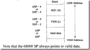
The 68000 accesses the system stack from the top for operations such as subroutine calls or interrupts. This means that stack operations such as subroutine calls or interrupts access the system stack automatically from HIGH to LOW memory. Therefore, the system SP is decremented by 2 for word or 4 for long word after a push and incremented by 2 for word or 4 for long word after a pop. As an example, suppose that a 68000-CALL instruction (JSR or BSR) is executed when PC = $0031F200; then, after execution of the subroutine call, the stack will push the PC as follows:
In 68000, stacks can be created by using address register indirect with postincrement or predecrement modes. Typical 68000 memory instructions such as MOVE to/from can be used to access the stack. Also, by using one of the seven address registers (AO-A6) and system stack pointers (A7,A7′), stacks can be filled from either HIGH to LOW memory or vice versa:
1. Filling a stack from HIGH to LOW memory (Top of the stack) is implemented with predecrement mode for push and postincrement mode for pop.
2. Filling a stack from LOW to HIGH (Bottom of the stack) memory is implemented with postincrement for push and predecrement for pop.
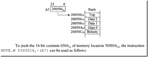
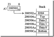
For example, consider the following stack growing from HIGH to LOW memory addresses in which A7 is used as the stack pointer:
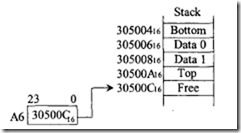
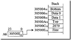
The 16-bit data item 050416 can be popped from the stack into the low 16 bits of D0 by using MOVE. W (A 7) +,D0. Register A 7 will contain 200504 16 after the pop. Note that, in this case, the stack pointer A7 points to valid data. Next, consider the stack growing from LOW to HIGH memory addresses in which the user utilizes A6 as the stack pointer:
To push the 16-bit contents 2070 16 of the low 16 bits ofD5, the instruction MOVE. w DS, (A 6} + can be used as follows. The 16-bit data item 2070 16 can be popped from the stack into the 16-bit contents of memory location 417024 16 by using MOVE. W – (A6) ,$ 417 0 2 4. Note that, in this case, the stack pointer A6 points to the free location above the valid data.


