Power Supplies
It is surprising to many people that you can add a simple voltage regulator to power your projects for just a few dollars; cheaper than a set of rechargeable batteries. Voltage regulators, powered by an AC/DC ‘‘Wall wart’’ power converter, will convert one DC voltage to another that can be used by the electronics in your circuit and, more importantly, will be tolerant of changes in the AC supply and the current load. In this section, I will
introduce you to some simple power supply circuits that have the following characteristics:
1. They are safe for their users and designers.
2. They are relatively efficient in terms of the amount of power that is lost converting voltage levels.
3. They provide very accurate voltage levels, independent of the voltage input or the current required by the application.
4. They are inexpensive.
5. Their design can be optimized for the application that they are providing power for.
6. These supplies source up to 1 amp of current.
The power supply ideas presented here are very appropriate for the simple circuits discussed in this book; the 250 watt power supply used for your PC requires methodologies and circuits for producing this much power that are quite a bit different than what is required for the simple power supplies presented here. Advanced degrees are normally required for properly designing high current power supplies that work at high efficiencies.
There are some semiconductor-based circuits, like Zener diode power supplies (Fig. 12-11) that do lend themselves to being modeled using water analogs. The Zener diode power supply works as a shunt regulator – applying a specified amount of current to a circuit at a rated voltage and shunting the rest away as wasted power.
When the term ‘‘shunt’’ is used, it is simply saying that excess voltage and current is turned away from the circuit. This concept can be illustrated with a water pressure regulator created from a catch basin with a hole at the bottom; water coming out of the hole is at a pressure which is determined by the depth of water in the basin. To maintain this depth (and bottom pressure), even though water is being drawn from the hole at the bottom, ‘‘source’’ water is continually poured into the basin. More water is pouring in than is expected to exit through the hole in the bottom, with the excess leaking out over the side. This is exactly how the Zener diode works, except
that extra current does not ‘‘leak out over the side’’ but is passed (or ‘‘shunted’’) through the diode. The diode itself is expected to be reverse biased when it is wired into the circuit and it will pass current through it to maintain a set voltage level at its anode (positive terminal). This property is known as ‘‘breakdown’’ and it is not unique to the Zener diode. All diodes will ‘‘breakdown’’ when a high enough reverse bias voltage is applied to them. The breakdown voltage for a Zener diode is usually specified to be in the range of 1.5–25 volts where the breakdown voltage for a typical diode (say the 1N4148/1N914 that I usually use) is 75–100 volts.
Specifying a Zener diode for use as a power supply in an application isn’t very difficult but it will require you to understand what your incoming power specifications are as well as what the required current is for the circuit being powered. The powered circuit’s voltage should be the same as the rating of the Zener diode. For 5 volt circuits, I use a Zener diode rated at 5.1 volts. Specifying the resistor that is to be used with the Zener diode as well as the Zener diode’s power rating can be somewhat complex. Care must be taken to ensure that the circuit has enough current to be powered in all circumstances, including if the input power ‘‘sags’’ (if it is powered by a battery that is discharging). To do this, some kind of ‘‘margins’’ must be designed into the circuit.
For this experiment, I would like to use a 5.1 volt Zener diode to act as a power supply for a LED circuit requiring approximately 10 mA to light the LED. The circuit is shown in Fig. 12-11 and, before it can be assembled, the value for the Zener diode’s current limiting resistor ‘‘R’’ must be determined. For a Zener diode power supply to be 100% efficient in terms of current (no current is shunted through the Zener diode), ‘‘R’’ must be chosen so that the voltage drop through it will allow the same amount of current as the powered circuit uses to pass through it. In this application, I am going to assume that the LED has a 2 volt drop, so using the basic electrical formulas, I can determine the current through the LED:
There are no standard 415 Q resistors available, but I can make a 420 Q resistor using a 200 Q and a 220 Q in series. This will result in a current of 9.29 mA (a difference of about 1% from the targeted value).
When I described the Zener diode regulator as acting like a basin of water in which the unused current was simply lost, I’m sure that many people grimaced because they knew of devices which are much better at regulating fluid pressure. If this book was written in the 1980s (or earlier) just about everybody would know about the commonly used fluid regulator that is used in older cars called a carburetor (Fig. 12-12). Virtually all cars built in the past 15 years have utilized some form of computer-controlled ‘‘fuel injection’’ which relies on active, rather than passive, control of the fuel being passed to the engine.
The carburetor is a very clever device that only provides fuel on demand. In Fig. 12-12, I have drawn the situation where no fuel is being drawn from the carburetor – a ‘‘float’’ is connected to a simple valve that closes when the fuel in the bowl that the float is in is full. When fuel is drawn from the bowl, the fuel level within the bowl drops (along with the float) and the valve opens, allowing more fuel into the bowl (Fig. 12-13). The carburetor is quite efficient and very simple in operation.
The carburetor acts as a regulator, just providing the volume of fuel (current) as required and the shallow bowl will result in lower pressure (pressure regulation) than what was available from the high-pressure source (the fuel pump). An electrical version of the carburetor would look
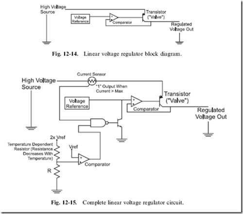
like Fig. 12-14; current from the high voltage source is switched through a PNP bipolar transistor, with the control of the transistor being the output of the comparator. The comparator’s inputs are the current voltage level of the regulator’s output and the specific ‘‘output’’ voltage which comes from some kind of voltage reference. The voltage reference is usually a Zener diode that has a miniscule amount of current passing through it; the comparator does not need a lot of current to operate.
Adding the current and temperature ‘‘crowbar’’ sensors is implemented something like in Fig. 12-15. When either the current output or temperature exceeds the preset limits, the reference voltage is pulled to ground using an NPN transistor (remember that the voltage reference is very low current so this can be done safely). In some regulators, if the current or temperature parameters are exceeded, they ‘‘latch’’ the failing state until power is removed and the crowbar conditions are reset. The need for the current sense and shut down should be pretty obvious to you; if the current drawn exceeds the
maximum rating for the PNP transistor, it could be damaged. The temperature sensor may be a bit more unexpected but shouldn’t be surprising when you consider what is happening in the regulator when it is transforming a high voltage into a lower one. The difference between the input voltage and the regulated voltage multiplied by the current being drawn by the circuit being regulated is the power dissipated by the regulator. For example, if you had a 12 volt voltage source and a 5 volt regulator providing 200 mA current, the power being dissipated by the regulator would be 1.4 watts. This level of power dissipation could damage the internal circuitry of the regulator or, at the very least, raise the temperature of the part so that it does not work as designed.
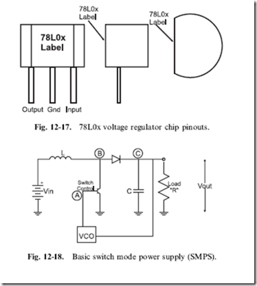
The most popular linear voltage regulators that provide the crowbar features are the 78xx and 78Lxx series. The 78xx (or the LM2940 series of regulators which have the same pinout and package) shown in Fig. 12-16 (‘‘xx’’ standing for the voltage, so a 5 volt regulator is a ‘‘7805’’) can normally source up to 500 mA and up to 1 A with heat sinking. The heat sink is used to dissipate the power and keep the temperature within the regulator less than 1258C, which is the crowbar temperature. For lower current applications (up to 100 mA), the 78Lxx (Fig. 12-17) can be used. For either device, the input voltage should be at least 2 volts above the regulated output voltage. When wiring the regulator in circuit, you should include at least 10 mF of capacitance on the input and a 0.1 mF capacitor on the output.
While the Zener diode and linear power supplies presented so far in this chapter are useful and easy to work with, they do have two concerns that can make them problematic when they are being used in a battery-powered application. First off, they require a higher voltage than the regulated output; this can be an issue when you want to use very simple power like two AA cells
for a digital electronics circuit. Secondly, they are not terribly efficient. It isn’t unusual for 80% or more of the power input to the Zener diode power supply to be lost and 40% or more lost in the linear power supply. What is required is a power supply circuit that is very efficient and will ‘‘step up’’ voltages.
While these two requirements seem impossible, they can actually be achieved very easily through the use of the ‘‘switch mode power supply’’ (SMPS). The basic SMPS circuit (Fig. 12-18) is quite simple and relies on the energy storing characteristic of the inductor or ‘‘coil’’. While the capacitor stores energy in the form of charge, the coil stores energy in the form of a magnetic field which is maintained by current running through the coil.
When this current is shut off, the magnetic field produces a voltage ‘‘spike’’ (which I called ‘‘kickback’’ when discussing magnetic devices) that can be used as the basis for an output voltage.
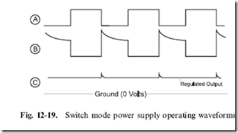
Using the circled letters in Fig. 12-18, I have drawn the waveforms (Fig. 12-19) that you can expect to see in the SMPS. The ‘‘Control’’ signal is a PWM produced by a ‘‘voltage controlled oscillator’’ (VCO). A voltage controlled oscillator oscillates at a different frequency based on the voltage at an input. The input to the VCO used in the SMPS is the output voltage
of the power supply; the VCO frequency will change according to the power supply output to ensure the output stays as stable as possible at the required voltage. The output of the VCO is the base of a transistor that periodically pulls one side of the coil to ground, allowing current to flow through it. When the transistor connected to the coil is turned off, current flow through the coil stops and the magnetic field ‘‘kicks back’’, producing a higher voltage.
The operation of the VCO PWM output along with the coil’s response and the output voltage is shown in Fig. 12-19. When the VCO is turning on the transistor, the coil (symbol ‘‘L’’) is tied to ground and current flows through it. When the transistor is off, the coil kickback can be seen and any voltage greater than the current voltage output from the supply passes through the diode and is stored in the output capacitor. As I said above, if the output voltage is more or less than the target voltage, the VCO frequency changes along with the transistor control PWM, bringing the output voltage into line.
To determine the correct coil value as well as the PWM parameters, the following three formulas are used once the output voltage (‘‘Vout’’) is known along with the expected output current draw (‘‘Iout’’) and the input voltage (‘‘Vin’’). These formulas are used repeatedly until the values for ‘‘L’’ (the coil value), ‘‘Ton’’ (time the transistor is on) and ‘‘Toff’’ (time the transistor is off) are values that can be produced by reasonable hardware.
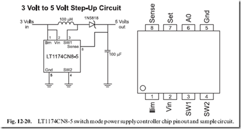
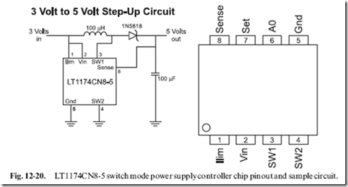
Designing an SMPS is not a trivial exercise. While you may think you can do it using something like a 555 timer, I’m going to recommend that you use a commercially available chip that provides the function for you, like the LT1173-5. This chip can be used to create 5 volts (neccesary TTL and
many CMOS logic chips) from 3 volts, as shown in the basic circuit in Fig. 12-20.
With the appropriate regulator selected, you now have to find a source of DC current to power the application and regulator. By far the most popular way of providing power to an electronic device is by simply plugging it into a wall socket.
I must caution you that the power coming out of your wall socket can conceivably destroy your application, cause a fire or hurt you (e.g. burns or electrocution). Despite the fact that it is commonly used for appliances, light and electronic devices in the home, electricity is not to be trifled with.
The circuits provided below may not be appropriate for where you live. The information provided here is strictly ‘‘rule of thumb’’ and is primarily written for use in North America. If you are going to design a power supply for a specific country’s use, make sure you understand what are the characteristics of the local power supply, along with any laws or regulations that are appropriate when connecting to it.
Power coming from your wall sockets (‘‘the mains’’), comes in as either a 110 or 220 volts ‘‘peak-to-peak’’ as a ‘‘sine wave’’ with a frequency of 50 or 60 cycles per second (or ‘‘hertz’’ (‘‘Hz’’)). In North America, power is provided at 110–120 volts peak-to-peak voltage (typically 115 volts) at 60 Hz. Different countries around the world will use different peak-to-peak voltage levels and operating frequencies.
This power coming in is normally provided by a ‘‘socket’’, which is built into your walls. Figure 12-21 shows the layout of the socket and labels the
individual connections. ‘‘Live’’ or ‘‘Hot’’ is the incoming alternating voltage sine wave shown in Fig. 12-21. ‘‘Neutral’’ is the return path for this current, while ‘‘Ground’’ is a shunt to ‘‘earth ground’’ if the circuit is damaged and the live voltage is passed to the neutral connection. If these three signals are being wired manually by convention, ‘‘Live’’ is black, ‘‘Neutral’’ is white and ‘‘Ground’’ is Green.
Because the AC voltage coming from the ‘‘mains’’ is so high and has
positive and negative voltage components, it has to be converted into a lower DC voltage for the electronics. This is done in three stages. The first is reducing the voltage from more than 100 volts to 15 volts or less using a ‘‘transformer’’. A transformer (Fig. 12-22) is a device made up of two coils that share their magnetic field. When current is passed through one coil, the second coil will produce an ‘‘inducted’’ voltage and current, which can be used to power the circuit. Figure 12-22 also gives the relationship between the voltage and current on the secondary side coil based on the number of turns for each coil.
Note that the current is inversely proportional to the turns ratio. In North America (which has 110 volts AC), an 8:1 transformer is often used. This means that with 110 volts in, there will be 14 volts out. For 220 volts, a 16:1 transformer should be used for the same voltage output.
While the voltage has been lowered, it is still ‘‘AC’’ and it is still going positive and negative. This voltage has to be ‘‘rectified’’ into a straight
DC voltage. This is done using diodes in either a ‘‘half wave’’ or ‘‘full wave’’ rectifier. Full wave rectifiers transform the positive and negative ‘‘lobes’’ of the AC circuit into a positive voltage, whereas the half wave rectifier ‘‘clips’’ the negative wave (providing half the total power available to the circuit). Inputting the rectified signal directly from the diodes into a voltage regulator should not be attempted; instead, a filtering electrolytic capacitor or a few tens of mF should be used. The filtered signal output from the full wave rectifier was shown in Chapter 3.
As long as the rectified signal does not drop below the minimum voltage of the Voltage Regulator, the regulated DC voltage output will be constant. The filtering cap should be a minimum of 10 mF with a good rule of thumb being that for digital circuits; a 20 mF capacitor is required for each Amp of current drawn. For DC electric motors, this value increases to 100 mF per amp drawn to help prevent inductive ‘‘kickback’’ ‘‘spikes’’ from being driven back through the transformer to the mains circuit.
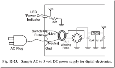
Using the transformer, full wave rectifier, an electrolytic filter capacitor and a 7805 voltage regulator, a þ5 volt 0.5 amp power supply for digital logic applications could be created, as shown in Fig. 12-23. The voltage regulator converts the rectified transformer-reduced AC voltage into a voltage that can be used by the digital logic.
There are a few things to note in Fig. 12-23. The first is that the mains ground is connected to the case and not to the ‘‘digital ground’’. In any DC- powered circuit, the negative terminal of the full wave rectifier can be called ‘‘digital ground’’, but should be left ‘‘floating’’ relative to ‘‘earth ground’’, which is provided by the AC plug. In this case, ‘‘digital ground’’ is simply a common negative terminal for the circuit. I have put a ‘‘fuse’’ in the power line, which will cut out in high current draw situations (like short circuits).
It is rated at 0.1 amps, which may seem low, but remember that current output is inversely proportional to the turns ratio of the transformer:
0.1 amps at 110 volts translates into 1.4 amps at 8 volts at the output. Without this fuse, very large (and very dangerous) currents could build up inside the circuit. For example, 2 amps at 110 volts translates to 28 amps at 8 volts or 224 watts of power. Along with the fuse, the ‘‘Switch’’ in the circuit should be one that is certified for switching AC voltages. AC switches usually have a mechanical assembly inside them that ‘‘snaps’’ the switch contacts on and off. This minimizes ‘‘arcing’’ within the switch. This may seem hard to believe, but if you look inside an AC switch while it is opening or closing, you will see a blue spark and sometimes hear a ‘‘pop’’. This is caused by high inductive voltages produced by the transformer coils that ‘‘kickback’’ when the AC power is shut off.
If you do build mains power supply circuits, like this one, I recommend that you use 14-gauge stranded wire for all connections. Connections should consist of soldered connections (not household ‘‘Marette’’ connectors) for safety. ‘‘Heat shrink tubing’’ should be placed over all solder joints and bare wire. As well, only UL/CSA (or the local country testing organization) approved plugs, wires, switches, fuse holders and transformers should be used in a properly grounded metal case.
If any of these terms are unfamiliar to you or you doubt your ability to build the circuit safely, then don’t build it!
Programmable Logic Devices
Programmable logic devices (‘‘PLDs’’) are chips which have logic gates and flip flops built in, but are not interconnected. The application designer will specify how the gates and flip flops are interconnected in order to create a portion of the application’s circuit. Most people feel that programmable logic devices are a relatively new invention, but they have been around for many years. It has only been quite recently (in the last 10 years or so) that reusable chip technology (i.e. EPROM and flash)-based PLDs have been available at prices hobbyists and small companies could afford.
There are several types of PLDs. The first is the simple array of logic gates and devices that are built of this type are known as ‘‘PALs’’ and ‘‘GALs’’ (I generically refer to them as ‘‘PALs’’). The chips themselves are quite simple and relatively easy to design circuits for. These circuits are normally arranged as a ‘‘sum of products’’ in which signals on the chip can be easily 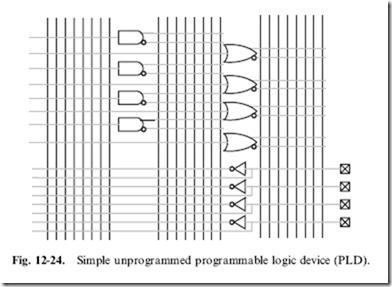
interconnected to form more complex logic functions. The chips are normally blocked out as a series of inputs and outputs, as shown in Fig. 12-24.
The vertical lines or ‘‘busses’’ in Fig. 12-24 are referenced to the gates and I/O pins they are connected to.
To form logic functions, the ‘‘sum of products’’ is used. In Fig. 12-24, a simple 4 I/O, 12 gate PAL is shown. Every output is driven on a bus in both positive as well as negative format. Connections are made between the gates and the busses to create logic functions.
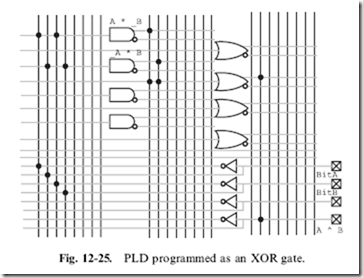
For example, the ‘‘XOR’’ gate which is characterized by:
which is not often available in standard logic. Taking Fig. 12-24 and connecting the busses to the different I/O pins and gates within the PAL, I can implement the XOR gate, as shown in Fig. 12-25.
Note in Fig. 12-25, that an I/O pin changes from an input to an output by simply connecting it directly to a gate output. This feature allows the pins to be used as either input or output.
Options for PALs include varying numbers of inputs to the internal AND and OR gates. For the PLD shown in Fig. 12-25, I have left open the option that any of the pins can be used for any purpose. This is a bit unusual and, normally in PALs, the number of inputs to a gate is restricted. Another
option is to include built in flip flops to store states and turn the PAL from a combinatorial circuit into a sequential one.
PALs may seem simple, but they can result in large decreases in the chip count for an application. In some cases, PALs may be more expensive than the chips they replace, but they reduce application power and board space chip requirements. These savings could result in all-over product savings. It is not unusual for 10 TTL chips to be replaced by a single PAL, resulting in huge PCB and power supply cost savings.
At the high end of the programmable logic device family range, some
devices are virtually ‘‘ASICs’’ (‘‘Application Specific Integrated Circuits’’) and use the same programming language (‘‘VHDL’’) and development tools as ASICs. These complex parts generally have their functions broken up into ‘‘macros’’. An ASIC/PLD macro can be an AND, or XOR not, logic gate, flip flops or collections of functions (such as multiplexors and arithmetic logic units) which simplify the task of circuit development and eliminate the need for wiring individual gates into basic functions.
The high-end programmable logic device’s programming information is
often directly transferable to the technology. This allows initial production to use programmable logic devices that require little cost to program and, when the design is qualified, ASICs can be built at a chip foundry for reduced per unit costs.
Programmable logic devices have the advantage of being able to
implement fast (less than 10 ns) logic switching, but they do not have the ability to store more than a few bits of data.
Often, programmable logic devices are used in proprietary circuits because their functions cannot be easily traced and decoded.
Programmable logic devices and ASIC development tools are generally function text based as opposed to graphically based applications (like a schematic drawing). This means that a text format, like the ‘‘XOR’’ definition above, must be used to define the functions. Most ‘‘compilers’’ for these statements are intelligent enough to pick the best gates within the device to work with and pick the best paths without your intervention. They are typically much more sophisticated (and expensive) than the compilers used for converting high-level program statements into instructions for a processor.
Quiz
1. The choices in processor design are:
(a) Intel vs AMD vs PowerPC
(b) CISC vs RISC, Princeton architecture vs Harvard architecture, hardcoded instruction execution vs state machine instruction execution
(c) TTL vs CMOS logic
(d) Speed vs minimal power consumption
2. Microcoded instructions are:
(a) Short instructions which take less time to execute
(b) Coded instructions that cannot be read by spies
(c) Instructions that are specific to a microprocessor
(d) State machine instructions outlining the steps needed to execute an instruction
3. Decimal 47.123 in binary is:
(a) Invalid; you cannot perform this conversion (b) B’101111.00011111’
(c) B’11111.101111’
(d) 0x02F.1F7
4. Which statement is false? ‘‘Flash’’ memory cells:
(a) Are designed from EPROM memory cells
(b) Can be erased by applying an electrical voltage
(c) Are built from flip flops
(d) Are limited to 256 bits in size
5. DRAM Memory is:
(a) Faster than SRAM memory
(b) Less expensive per bit than SRAM memory
(c) More reliable than SRAM memory due to ‘‘refreshing’’
(d) More expensive per bit than SRAM memory
6. What is not a feature of the DC/DC power regulators presented in the book?
(a) They will convert AC to DC directly
(b) They have current limiting capability
(c) They have temperature limiting capability
(d) They have voltage ‘‘Brown out Reset’’ capability
7. With 12 volts coming in, the current limiting resistor for a 5 volt, 200 mA Zener diode:
(a) Insufficient information to calculate the resistor’s parameters
(b) 3.5 Q, 10 watt
(c) 350 Q, 1 watt
(d) 35 Q, 2 watt
8. A switch mode regulator needs the following components to work:
(a) Capacitors, diodes and inductor
(b) Capacitor, diode and PWM driver
(c) Capacitors, diode, transistor, PWM driver and inductor
(d) Comparator, PWM driver, transistor and inductor
9. ‘‘PAL’’ is the acronym for:
(a) Pound and lever
(b) Peripheral aspect light
(c) Partial AND logic
(d) Programmable array logic
10. VHDL is used for:
(a) Defining PLD electrical parameters
(b) Defining PLD gate requirements
(c) Defining PLD gate operations
(d) Defining PLD speed parameters


