Screen Efficiency
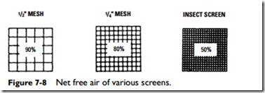
It is frequently necessary to cover an air intake (or exhaust) area with a bird or insect screen. These screens reduce the free intake area, but the amount of the reduction will depend on the type of screen used. In Figure 7-8, the net (effective) free area for each of three screens is shown as a percentage. The small holes required by an insect screen reduce the net free area to approximately 50 percent. The 1⁄2-inch mesh screen, on the other hand, provides a net free area of 90 percent.
The reduction of the free intake area by screens can be compen- sated for by using a larger overall area.
Static Pressure
The static pressure of a fan may be defined as the total pressure diminished by the fan velocity pressure.
Calculating the total external static pressure of a system is important to the selection of a fan or blower because it must be capable of handling the required volume of air (in terms of cfm) against this pressure.
The total external static pressure is determined by adding the static pressures of any of the air-handling components in a system capable of offering resistance to the flow of air. A 10 percent allowance of the sum of these static pressures is added to obtain the total external static pressure.
The static pressures (that is, friction losses in inches of water) used in determining the total external static pressure of an air-han- dling system will include the following:
1. Entrance loss
2. Friction loss through filters
3. Friction loss through tempering coils
4. Friction loss through air washer
5. Duct system resistance
6. Supply grille resistance
Most friction losses can be obtained from data tables provided by manufacturers; however, duct loss is based on the longest run of duct, and this will vary from one installation to another.
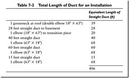
In determining the length of duct, start at the point where the air enters the system and include all ducts in the main supply duct to the end of the system. An example of this type of calculation is shown in Table 7-2. The sum (406 ft) is then multiplied by the
resistance for the ducts. For example, if the resistance is found to be 0.1 inch per 100 feet, the static pressure for the total run of duct will be 0.406 inch (that is, 406 ft –: 100 ft = 4.06 ft X 0.1 in = 0.406 in).

