Upfeed One-Pipe Relief System
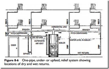
Figure 8-6 shows an upfeed, one-pipe, relief system applied to an eight-radiator installation. Connected to the main outlet A are two or more branch mains AB and AC, which supply the various risers.
Steam is supplied to each riser, and the condensate drains in the riser in reverse direction to the steam flow.
The condensate returns from the risers to the boiler by gravity through drip pipes (or drop pipes), which are virtually continua- tions of the return pipe, so that the condensate will flow back into the boiler.
Steam (usually at 1 to 5 psig) passes from the boiler to mains AB and AC. These branches being slightly inclined, any condensate will drain into the drip pipes. The steam passes through the risers to the radiators, where its heat is radiated to warming the rooms, thus causing condensation. Because the risers are sufficiently large, the condensate is carried by gravity in a direction reverse (that is, opposite) to the direction of the steam flow, drains down the drip pipes, and returns to the boiler through the low- level (wet) return pipe.
The condensate is forced back into the boiler by the pressure resulting from the greater head of the column of condensate in the drip pipes, as compared with the head of water in the boiler. Moreover, the water in the drip pipes, being at a lower temperature than the water in the boiler, is heavier, which upsets the equilibrium of the two columns.
This system is characterized by a slight difference in pressure (pressure differential) in the various parts of the system caused by frictional resistance offered by the pipe to the flow of the steam.
The steam flow is variable in different parts of the system due to variable condensation and badly proportioned pipe sizes. This can be explained by Figure 8-6. If the water level in the boiler is at D, then in operation with wet returns, the pressure difference will be balanced by the condensate standing at different levels in the differ- ent drip pipes, as at E and F, these levels being such that the differ- ence in head and density will restore equilibrium. The effect of a wet return can be obtained with the dry return (shown at the left in Figure 8-6) by attaching a siphon to the bottom of the drip pipe. Water from the drip falls into the loop formed by the siphon; and after it is filled, it overflows into the dry return.
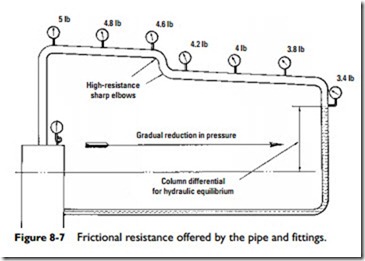
The water will rise to different heights, G and H, in the legs of the siphon to balance the difference in pressure at points P and P‘. If the siphon were omitted and the drip pipe connected directly to the dry return, there would be a tendency for the condensate in the dry return to back up instead of draining into the boiler because the pressure in the drip pipe at P is greater than the pressure in the dry return. In general, the pressure varies because there is a gradual reduction in pressure as the steam flows from the boiler to the remote parts of the system. This is caused by frictional resistance offered by the pipe and fittings (Figure 8-7).
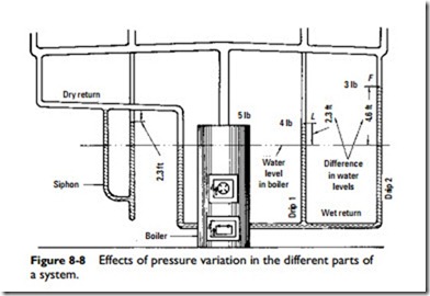
The steam flows into the pipes only when condensation is taking place. The variation in pressure exists, on the other hand, only when the steam is flowing in the pipes. The effects of pressure variation can be explained with the aid of Figure 8-8. With the plant in oper- ation and condensation taking place in the radiators and condensate draining into the drip pipes (suppose the pressure in the boiler is 5 psig—4 psig in drip 1 and 3 psig in drip 2), then to balance these pressure differences the water will rise in drip 1 to L 2.3 ft above the water level in the boiler, because there is a pressure difference of 1 psig (5 – 4) and the weight of a column of water 2.3 ft high is 1 lb for each square-inch of cross-section. Similarly, for drip 2, the pres- sure difference is 2 psig; hence, the water will rise in this column to an elevation above the water level in the boiler equal to 2.3 X 2, or 4.6 ft, to balance the 2-psig pressure difference. Strictly speaking, these figures are correct only when the temperature of the water in the two drip pipes is the same as the temperature of the water in the boiler. For simplicity, the difference in weight or density of the cold water in the drips and hot water in the boiler were not considered. Under these circumstances, the heavy cold water in the drips would rise to lower elevations than those shown at L and F in Figure 8-8.
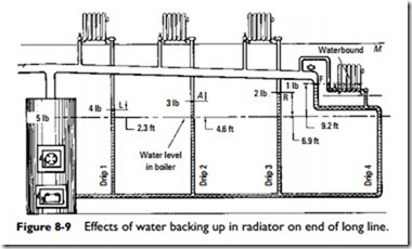
Sometimes there are problems encountered on long lines with radiators located at the end of the line and near the level of the
water in the boiler. On long lines where there is considerable reduction of pressure, the water sometimes backs up into the radiator, as in Figure 8-9, interfering with its operation.
Radiators located at elevations below the water level in the boiler may be operated by means of a steam loop (Figure 8-10). In the steam loop, the condenser element may consist of a pipe radiator placed on the floor above the boiler. The ample condensing surface thus provided will render the loop very active in removing the condensate, and at the same time the heat radiated from the condenser is utilized in heating. The drop leg is pro- vided with a drain cock D, and the connection to the boiler is provided with a check valve. To start the system, turn on the steam at the boiler and open D until the steam appears. The condensation of steam in the condenser (upper radiator) will cause a rapid circulation in the riser, carrying with it the condensate from the lower radiator, which, in passing over the goose neck, cannot return but must gravitate through the upper radiator and drop leg past the check valve and into the boiler. The pipe at the bot- tom of the main riser, which acts as a receiver for the condensatie from the lower radiator, should be one or two sizes larger than the pipe in the main riser.


