Gas Turbine: Brayton Cycle
The Brayton cycle (George Brayton, 1830-1892) is an internal combustion cycle based on a gas turbine. Schematic and T-s-diagram are depicted in Fig. 10.7. Environmental air at p1 = p0, T1 = T0 enters the compressor in which it is adiabatically compressed to the pressure p2. As the air flows through the combustion chamber, fuel is injected and burnt with some of the air’s oxygen which leads to heating of the air. The pressurized hot combustion product expands in the turbine and delivers work; some of the work is required to drive the compressor. The expanded combustion product exhausts to the environment.
As for the reciprocating internal combustion engines, we shall ignore the addition of fuel, and the change of composition through the chemical reaction, and treat the working fluid as air. Then, the combustion is described as an isobaric heating process. The turbine exhaust is warmer than the environment, and exchanges heat with the environment at T0. The discharge of hot air (state 4) and the intake of cool air (state 1) can be described as an isobaric cooling process at p1 = p4 = p0; this process is indicated in the schematic as dotted line.
The Brayton cycle is the equivalent to the Rankine cycle for the ideal gas, and the basic analysis is similar. The main differences are that the Brayton cycle operates without phase change, has no cooler or condenser, and that its back-work-ratio is much larger than that of the Rankine cycle.
Work and heat for the four processes are
The total power produced, the heat consumed, and the heat rejected by the cycle follow after multiplication with the mass flow m˙ as
To gain further insight into which parameters are most important, we consider the reversible cycle operating under the cold-air approximation (air as ideal gas with constant specific heats), for which we find the thermal efficiency as
The thermal efficiency of the gas turbine increases with the pressure ratio P = p2/p1.
We proceed by studying operating conditions of gas turbine systems. Obviously, the inlet pressure and temperature, p1 and T1, are set by the environmental conditions, p0 and T0. The highest temperature in the cycle is the turbine inlet temperature T3 which is limited by the materials used for the turbine. For fixed values of T1 and T3, the work per unit mass of air for the gas turbine is
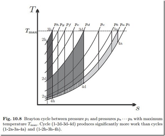
Figure 10.8 shows Brayton cycles in the T-s-diagram. All cycles share the intake pressure p1 and the maximum temperature Tmax, but their upper pressures (pa, pb,.. .) differ. The specific work is the area enclosed by the cycle in the T-s-diagram, and the figure shows that the cycle with the largest upper pressure (ph), which has the largest efficiency, has a low work output. Also the cycle with the smallest pressure (pa), which has the smallest efficiency, has low work output, while a cycle with intermediate pressure (pd) has the largest work output.
The goal is to produce a certain amount of power W˙ = m˙ w8. A gas turbine with small specific work but large efficiency must have a larger mass flow than a turbine with larger specific work. Larger mass flow can only be achieved by building a bigger system, or several smaller systems, which adds capital and maintenance costs. Normally, one will chose to operate a gas turbine close
to the maximum work output, where the thermal efficiency is smaller, but capital and maintenance costs are smaller as well.
The maximum of the specific work is found, from the condition dw8 = 0, for the pressure ratio
From the above it is clear that increase of the turbine inlet temperature T3 will increase work output and thermal efficiency. The use of modern materials and the cooling of turbine blades by pressing cold air through small channels in the blades have led to dramatic increases of turbine inlet temperatures which can be as high as 1700 K for airplanes at take-off.
For simple gas turbine systems, the hot exhaust is just expelled into the environment, where it equilibrates by heat transfer to the environment at T0. This process is associated with external entropy generation, the corresponding work loss is
Figure 10.8 shows that the turbine exit temperature T4 decreases with in- creasing pressure ratio. This implies that the external loss becomes smaller with increasing pressure ratio, and hence explains why the cycle efficiency increases.
As can be seen from the T-s-diagrams in Figs. 10.7, 10.8, the exhaust temperature T4 lies above the environmental temperature T1, and may also lie above the pre-combustion temperature T2. In advanced gas turbine cycles, the hot exhaust is used to preheat the compressed gas before combustion (regenerative Brayton cycle, Sec. 13.4), or as heat source for a steam power plant (combined cycle, Sec. 13.6). With this, the hot exhaust is used, and the external loss is reduced.


