SCHEMATIC 2
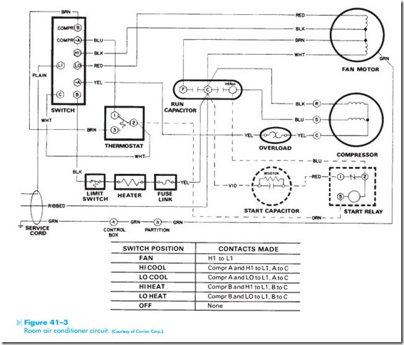
The second schematic to be discussed is shown in Figure 41–3. This schematic is for another room- type air conditioner, but it has some added components. This unit is used to provide heat as well as cooling. An electric resistance heating element is used to provide heat in cool weather. Notice also the addition of the start capacitor and start relay. The thermostat in this circuit is double-acting instead of a single-pole single- throw. This permits the same thermostat to be used for both heating and cooling. Notice also that the run capacitor is different. This capacitor is actually two capacitors contained in the same case. The junction point between the two capacitors is connected to one side of the service chord. The fan motor in this unit is different also. Notice that this fan used a run capacitor connected in series with the start winding of the motor at all timers. This motor is a permanent split-capacitor motor. Notice that this motor has two speeds instead of three.
The start capacitor is connected in parallel with the run capacitor to increase the starting torque of the compressor. The resistor shown connected across the terminals of the start capacitor is a relatively high value of fixed resistance used to dis- charge the capacitor when it is disconnected from
the circuit. Notice the start relay. The start capacitor is connected in series with the normally closed con- tact. This is a potential starting relay, which senses the voltage induced in the start winding and opens the contact when the motor reaches about 75% of its full speed.
In this circuit, the switch is the main controller. For example, trace the circuit when the switch is placed in the high cool position. The legend at the bottom of the schematic indicates that when the switch is in the HI cool position, terminals COMPR A and HI are connected to terminal L1, and terminal A is connected to terminal C. When HI is connected to L1, the fan motor will operate in its high speed. When terminal COMPR A is connected to L1, a current path is provided to terminal 1 of the thermostat. Terminal 2 is connected to terminal C of the switch. Since switch terminal A is connected to switch terminal C, power is connected to the compressor motor through the thermostat contact. When the thermostat is connected in this manner, an increase in temperature will cause the thermo- stat contacts to close and a decrease in temperature will cause them to open.
Now assume that the switch has been set to the low heat position. The switch legend indicates that terminals COMPR B, and LO are connected to L1, and terminal B is connected to terminal C. When LO is connected to L1, the fan motor operates in the low speed position. When terminal COMPR B is connected to L1, power is provided to terminal 3 of the thermostat. Terminal 2 is connected to terminal C of the switch. Since switch terminal B is connected to the resistance heater through the high limit switch and fuse, the thermostat controls the operation of the heater. When the thermostat is connected in this manner, a decrease in temperature will cause the thermostat contacts to close and an increase in temperature will cause them to open.
