Stoker Construction
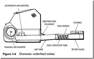
Although there are variations in the type and design of domestic stokers, the general features are much the same. An elementary stoker is shown in Figures 3-5 and 3-6, which gives the essentials and the names of parts. These parts may be listed as follows:
1. Retort.
2. Fan.
3. Motor.
4. Transmission.
5. Air duct.
6. Air control.
7. Hopper.
8. Feed worm.
9. Bin.
The retort is a firepot cast in a round or rectangular trough- like shape in which the coal is burned. It is made of cast iron and is surrounded by the windbox. The retort is provided with a number of air ports, or tuyeres, through which air for combustion is supplied.
The purpose of the fan is to supply forced draft, which is directed to the windbox that surrounds the air ports in the retort. This fan is commonly of the squirrel-cage type.
The air enters the retort through the ports via the air duct from the fan and the windbox that surrounds the retort. The fan is equipped with either manual or automatic control in the form of a damper at either the discharge or intake end. The air supply is con- trolled by means of these fan controls.
Coal stokers are designed to operate on either high- or low-air- pressure systems. In the high-air-pressure system, the air is forced in small jets into the fire area. A major disadvantage of this type of system is that the coal sometimes tends to fuse, causing clinkers to form and wasting some of the combustible matter of the fuel. A low-air-pressure system tends to produce a more complete circula- tion of burning gases to all heat-inducting surfaces.
A stoker is usually powered with an electric motor, which operates both the coal feed worm and the fan. The stoker drive consists
of a transmission, a shear pin (or clutch throw-out), pulleys, belts, and related components. The purpose of the shear pin is to protect the driving mechanism against damage in case large foreign objects get mixed up with the coal.
The transmission rotates the coal feed worm at the proper speed to feed the amount of coal required. The construction is such that the rate of feed can be changed as desired.
The two kinds of transmission usually employed in stokers are the continuous drive, which is operated by means of reduction gears, and the intermittent drive, which operates with a ratchet. Another drive used in stoker transmissions is the hydraulic (usually referred to as an oil drive), which operates by regulating the oil pressure on the driving mechanism to control the number of revolutions the feed screw makes per minute.
The feed worm (sometimes called the feed screw) carries the coal from the hopper to the retort (firepot). It is geared to the transmission, its rate of revolution depending on the desired feed rate. The feed worm extends from the coal supply in the hopper or bin, through the coal feed tube into the retort, where the coal it carries is discharged.
Ashpits can be constructed so that they are located directly below the furnace or boiler (see Figure 3-7). The ashes are auto- matically deposited into the pit as the coal is burned. If the pit is designed large enough, the ashes will need to be removed only once or twice a year. It is recommended that the ashpit be constructed so as to permit removal of ashes from outside the house. This will result in a much cleaner and more convenient operation in the long run. Always vent the ashpit to the chimney or outdoors.
Some stokers (e.g., the Drawz stoker illustrated in Figures 3-2 and 3-3) are designed to permit hand-firing in case of power failure. In these situations, a natural draft may be provided by opening the grate and ashpit door.
