Room Air Distribution Systems
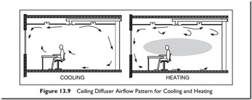
In mixing ventilating systems, the air is supplied, typically at 55–57°F, at a velocity of over 100fpm, (feet per minute), through an outlet diffuser or grill, at the ceiling or high in the sidewall. The objective is to have the supply air entrain and circulate the room air, to achieve good mixing. Figure 13.9.
The flow from a typical ceiling diffuser has a velocity profile as shown in Figure 13.9. The air velocity falls as more room air is entrained and the design should have the velocity no higher than 50 fpm in the occupied zone. When cooling, as shown on the left in Figure 13.7, the cool air is blown out across the ceiling and, although cool and dense, does not immediately drop due to the “Coanda” effect. The Coanda effect is the property of air to stay against a surface. For the cool air to drop from the ceiling, room air would have to move in above it, since otherwise a vacuum would be formed. This takes time to occur, with the result that the cool supply air travels far further across the ceiling before dropping than would the same flow if it had been discharged well below the ceiling.
The ceiling diffuser works well in the cooling mode. Unfortunately, it does not work very well in heating mode, since the warm, less dense, supply air stays up at the ceiling, out of the occupied zone. The buoyancy effect is particularly problematic with the supply air temperature more than 15°F higher than the general room temperature. The flow is shown on the right of Figure 13.9. The air enters the room and stays at the ceiling level except where the cool window creates a downdraft that provides a cool to cold draft over the occupants’ feet.
Mixing works well for cooling and can produce an even temperature throughout the space. Disadvantages include:
e The air velocity has to be low enough throughout the occupied area to avoid drafts, so there is a tendency for inadequate air movement in some areas.
e Any pollutants in the space can be spread throughout the space.
e All loads must be absorbed within the mixed air.
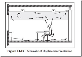
Displacement ventilation is the opposite of mixing. Displacement ventilation aims to avoid mixing in the occupied zone. Air, a little cooler than the space, is introduced at a low velocity (<100 fpm) through large area diffusers in the wall close to the floor. The air flows slowly and steadily across the space until it passes a warm object–a person or a piece of equipment. The warmth causes some of the air to rise up out of the occupied zone carrying pollutants and heat with it. Above the occupied zone, mixing occurs and the return outlet at the ceiling level draws the some of the mixed air out of the space. The flow pattern is shown in Figure 13.10.
The air supplied cannot be more than about 7°F less than the occupied space temperature, in order to avoid excessive cooling on the people closest to the outlets. This restriction severely limits the effective cooling capacity of the system. For cooler climates, such as Scandinavia, where the system is very popular, this load restriction is not as significant. Where higher internal loads must be absorbed, there are methods of entraining room air into the supply air to increase the effective flow into the room while still staying within 7°F less than room temperature.
The air movement in the space separates into the lower displacement zone with a recirculation zone above. In a well-designed space, the recirculation zone is just above the occupied zone.
The objective of the system is to have the occupants and the equipment in a flow of clean air, with their own heat causing convection around them. This will lift their pollutants up, out of the occupied zone. In addition, the convection heat from surfaces and lights above the occupied zone do not affect the temperature in the occupied zone. As a result the air leaving the room can be warmer than would be acceptable in the occupied zone.
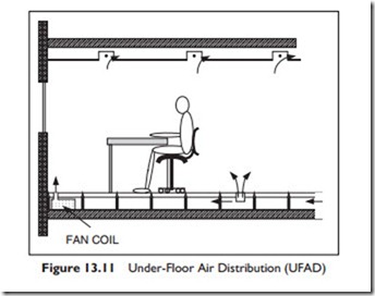
Under Floor Air Distribution, UFAD, is supplied from a raised floor through numerous small floor grilles. The floor typically consists of 24 inch square metal plates, or tiles, supported by a 10–18 inch high supporting leg, or column, at each corner. Some of the tiles have outlet grilles installed in them. The tiles can be lifted and moved around, making grille re-location, addition, or removal, a simple task as shown in Figure 13.11.
Air, at 58–64°F, is supplied to the cavity and discharges through the floor grilles. The floor grilles are designed to create mixing, so that the velocity is below 50 fpm within 4 feet of the floor. You can think of the air as turbulent
columns spreading out above the 4-foot level to form a vertical displacement flow towards the ceiling. Return air is taken from the ceiling or high on the wall. The rising column of air takes contaminants with it up and out of the breathing zone. This sweep-away action is considered more effective rather than mix-and-dilute. As a result, the ventilation requirements of ASHRAE Standard 62.1 can be satisfied with 10% less outside air.
There are numerous outlets, since the individual outlet volume is typically limited to 100 cfm. The entering air does not sweep past the occupants, as occurs in displacement ventilation, so there is no restriction on cooling capacity. There is, however, a limit on how well the system will work with rapidly changing loads. For spaces with high solar loads, thermostatically controlled fans or other methods are required to modulate the capacity to match the changing load.
Since the air is rising towards the ceiling, the convection heat loads above the occupied zone do not influence the occupied zone temperature. Therefore, the return air temperature can be warmer than the occupied zone and a return air temperature sensor is a poor indicator of occupied zone temperature.
The cool air flows continuously over the structural floor that somewhat acts as a passive thermal storage unit. This storage can be used to reduce peak loads.
For perimeter heating, small fan-coil units can be installed under the floor, using finned hot water pipes or electric coils. In a similar way, conference rooms that have a highly variable load can have a thermostatically controlled fan to boost the flow into the room when it is in use.
A modification of the under-floor system with individual grilles is the use of a porous floor. The floor tiles are perforated with an array of small holes, and a porous carpet tile allows air to flow upwards over the entire tile area. This is a modification of the standard grill and has yet to gain popularity.
The under-floor air delivery system has the following advantages:
e Changing the layouts of partitions, electrical and communications cables is easy. For buildings with high “churn” (frequent layout changes) this flexi- bility may, in itself, make the added cost of the floor economically justified.
e The flow of air across the concrete structural floor provides passive thermal storage.
e When the main supply duct and branches to the floor plenums are part of a well-integrated architectural design, the air supply pressure drop can be very low, resulting in fan-horsepower savings.
e Less ventilation outside air can potentially be used.
Disadvantages include:
e A significant cost per square foot for the floor system supply, installation and maintenance.
e A tendency to require a greater floor-to-floor height, since space for lights and return air ducts is still required at the ceiling level.
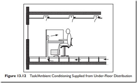
Our fourth and final type of air distribution system is most often a variation of the under-floor system. It is the Task\Ambient Conditioning system, TAC. With TAC each occupant workstation is supplied with cooling air and a degree of control over this airflow, airflow direction and temperature, as shown in Figure 13.12. In a typical arrangement one, or two, supply air nozzles are mounted above the work surface. The occupant can easily alter the velocity and direction of flow. Temperature may be controlled by mixing room air into the supply air, or by a resistance or radiant electric heater controlled by the occupant.
The ability to control their own environment is very popular with the occupants, though the measured conditions are not greatly different from occupants in the same building without a TAC. One specific advantage of the TAC for the occupant is the ability to modify the air speed. Since this system is in addition to the under-floor supply, there is significant research work being done to prove that the cost is more than recovered in improved staff productivity.
This completes our look at supplying air to occupied spaces. As with so many issues in HVAC, the climate and the local norms and experience will often drive decisions as much as technical merit.
Having discussed room air distribution we are now going to move to the other end of the system, where the ventilation air is brought into the building through the air handler.


