A Commercial Air Conditioning Unit
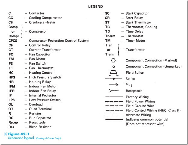
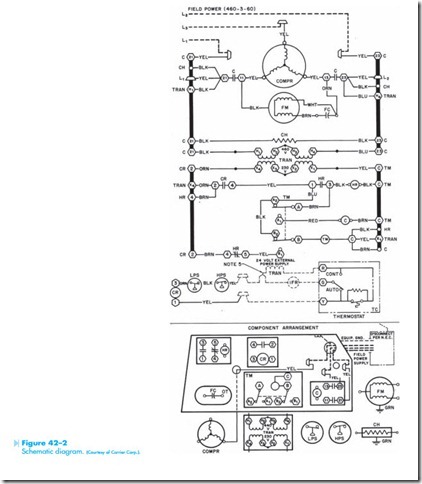
In this unit, a commercial air conditioning system will be discussed. The legend for this schematic is shown in Figure 42–1. The schematic to be discussed is shown in Figure 42–2. Notice that this control system contains several devices not normally found in a residential system. The compressor, for example, is operated by a three-phase squirrel- cage induction motor. It can be seen that the motor is three phase by the wye connection of the stator winding. It can be determined that the motor is a squirrel cage because it has no external resistors that would be used for the rotor circuit of a wound rotor induction motor. There is also no DC circuit that would be required to excite the rotor of a three- phase synchronous motor.
The condenser fan motor is a single-phase permanent split-capacitor motor. Notice that the con- denser fan motor is connected in parallel with two
lines of the compressor. When contactor C energizes, both C contacts close and connect both the compressor and condenser fan motors to the line.
The crankcase heater is shown directly below the condenser fan motor, and is connected to terminals 21 and 23. Notice the crankcase heater is energized at all times. As long as power is connected to the circuit, the crankcase heater will be energized.
The control transformer contains two primary windings and two secondary windings. This transformer can be connected to permit a 460- or 230-volt connection to the primary, and the secondary can provide 230 or 115 volts. In the circuit shown, the primary winding is connected in series, which permits 460 volts to be connected to it. The secondary winding is also connected in series, which provides an output voltage of 230 volts.
The 230-volt circuit is used to operate a short- cycle timer circuit. This is the same circuit that was discussed in Unit 35.
The 24-volt circuit is shown at the bottom of the schematic. Notice that only the secondary of the transformer is shown. This is indicating that its power can be derived from almost anywhere. The primary of this transformer could be connected to a 120-volt circuit inside the building. This circuit contains the high- and low-pressure switches. If one of them should open, it will have the same effect as opening the thermostat.
Notice that the indoor fan relay (IFR) is shown, but the fan motor is not. In a commercial location, there may actually be several fans operated by the IFR relay. In practice, the IFR relay may be used to control the coils of other relays, which connect the fan motors to the line.
The thermostat is a single-pole single-throw con- tact. The resistor shown connected around the thermostat contact represents the heat anticipator. A switch is also provided that will permit the indoor fan to be operated automatically or manually.
The last item shows the component arrangement. This is used to aid the service technician in locating the different control components in the system.

