USING AN AMMETER
The ammeter is used to measure the actual amount of electricity flowing in a circuit. This can be extremely valuable when trying to determine if something
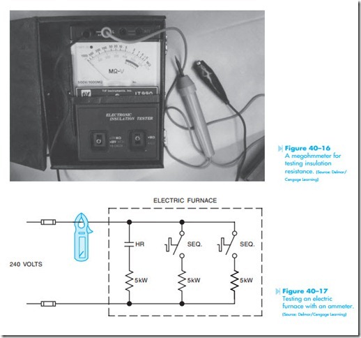
is actually operating or not. Assume that you are troubleshooting an electric furnace. Also assume that the furnace has three stages rated at 5 kW each. The stages are generally sequenced so they come on one at a time. A very fast method of checking the furnace is to connect a clamp-on ammeter to the incoming line, turn on the heat, and watch the readings on the ammeter, Figure 40–17.
Because each element has a power rating of 5,000 watts, the ampere draw of each element can be determined using Ohm’s law.
When the furnace is energized, the ammeter should indicate a current flow of approximately 21 amperes. After a few minutes the current should increase to approximately 42 amperes (20.8 + 20.8 = 41.6), and after another delay the current should increase to approximately 62.5 amperes (20.8 X 3 = 62.4). A voltmeter could be used to determine if voltage is being applied to each element, but unless the power was turned and off and the heating elements disconnected and tested with an ohmmeter, you could not be certain an element was not burned open. The ammeter permits a quick check of the unit and you know that each element is operating.


