The PN Junction
As stated previously, solid-state devices are made by combining P- and N-type materials together. The device produced is determined by the number of layers of material used, the thickness of the layers of material, and the manner in which the layers are joined together. Hundreds of different electronic devices have been produced since the invention of solid-state components.
It is not within the scope of this text to cover even a small portion of these devices. The devices to be covered by this text have been chosen because of their frequent use in the air conditioning industry as opposed to communications or computers. These devices are presented from a straightforward, practical viewpoint, and mathematical explanation is used only when necessary.
The PN junction is often referred to as the diode. The diode is the simplest of all electronic devices.
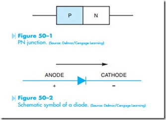
It is made by joining together a piece of P-type material and a piece of N-type material. Refer to Figure 50–1. The schematic symbol for a diode is shown in Figure 50–2. The diode operates like an electric check valve in that it will permit current to flow through it in only one direction. If the diode is to conduct current, it must be forward biased. The diode is forward biased only when a positive voltage is connected to the anode and a negative voltage is connected to the cathode. If the diode is reverse biased, the negative voltage connected to the anode and the positive voltage connected to the cathode, it will act like an open switch and no current will flow through the device.
One thing the service technician should be aware of when working with solid-state circuits is that the explanation of the circuit is often given assuming conventional current flow as opposed to electron flow. The conventional current flow theory assumes that current flows from positive to negative as opposed to the electron flow theory, which states that current flows from negative to positive. Although it has been known for many years that current flows from negative to positive, many of the electronic circuit explanations assume a positive to negative current flow. There are several reasons for this. For one, ground is generally negative and considered to be 0 volts in an electronic circuit. Any voltage above or greater than ground is positive. Most people find it is easier to think of something flowing downhill or from some point above to some point below. Another reason is that all the arrows in an electronic schematic are pointed in the direction of conventional current flow. The diode shown in Figure 50–2 is forward biased only when a positive voltage is applied to the anode and a negative volt- age is applied to the cathode. If the conventional current flow theory is used, current will flow in the direction the arrow is pointing. If the electron theory of current flow is used, current must flow against the arrow.
A common example of the use of the conventional current flow theory is the electrical systems of automobiles. Most automobiles use a negative ground system, which means the negative terminal of the battery is grounded. The positive terminal of the battery is considered to be the “HOT” terminal, and it is generally assumed that current flows from
Schematic symbol of a diode. (Source: Delmar/Cengage Learning)
the “HOT” to ground. This explanation is offered in an effort to avoid confusion when troubleshooting electronic circuits.
