Oil pressure failure switch
This is generally used with compressors incorporating oil pumps and on multiple compressor systems. The function of the control is to stop the compressor(s) when the oil pressure developed by the pump falls below a specific level, or if the oil pressure fails to reach a maximum safe level within a desired period after starting.
The oil pressure, as measured with a gauge, is the sum of the crankcase pressure (suction) and the pressure developed by the pump. The failure switch should be set to operate at the ‘useful’ pressure, and not at the total pressure. To determine the useful pressure (assuming correct compressor lubrication), subtract the suction pressure from the total pressure. Since the oil pump functions only when the compressor operates, the total pressure will be equal to the crankcase pressure during off cycles.
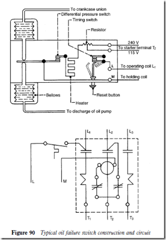
When the compressor starts, the oil pressure rises to the cut-in point of the switch. The differential switch will open and break the circuit to the heater, and the compressor will operate normally (see Figure 90).
If the useful pressure does not rise to the cut-in point within the time limit (60 to 180 seconds), the differential switch contacts will not open and the
heater will stay in circuit. This causes a bimetal strip in the timing relay to warp and open the timing contacts, which will break the circuit to the starter coil and stop the compressor. Similarly, if the useful pressure falls below the cut-in point during operation, the differential switch will close and energize the heater. The timing relay will stop the compressor after the time delay characteristic of the switch.
Controls are available with 60 and 90 seconds delay, but it must be realized that the time is not variable.
Most current production oil pressure failure switches are provided with terminals for the connection to a crankcase heater. Since the terminal arrangements vary, reference should be made to the wiring diagram provided with the switch.
Related posts:
Incoming search terms:
- danfoss oil pressure switch wiring diagram
- A diagram of current flow in Oil pressure switch
- components of oil switch
- danfoss refrigerant pressure switch for chiller
- differential oil pressure switch for hvac
- hvac how to wire oil pressure switch
- p77aaa-9301 circuit diagram
- the oil pressure of a compressor is determined by measuring _______ and ______ combined and subtracting _______
- what is hvac oil pressure switch
