The Triac
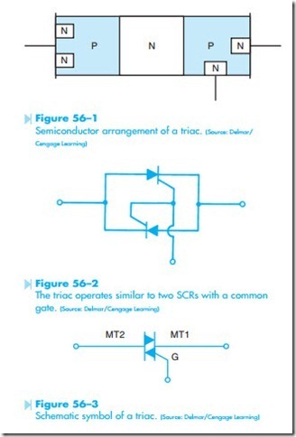
The triac is a PNPN junction connected in parallel with an NPNP junction. Figure 56–1 illustrates the semiconductor arrangement of a triac. The triac operates similar to two SCRs in parallel, facing in opposite directions with their gate leads connected together, Figure 56–2. The schematic symbol for the triac is shown in Figure 56–3.
When an SCR is connected in an AC circuit, the output voltage will be DC. When a triac is connected in an AC circuit, the output voltage will be AC. Since the triac operates like two SCRs connected together and facing in opposite directions, it will conduct both the positive and negative half cycles of AC current.
When a triac is connected in an AC circuit as shown in Figure 56–4, the gate must be connected to the same polarity as MT2. When the AC voltage applied to MT2 become positive, the SCR, which
is forward biased, will conduct. When the voltage applied to MT2 becomes negative, the other SCR is forward biased and will conduct that half of the waveform. Since one of the SCRs is forward biased for each half cycle, the triac will conduct AC current as long as the gate lead is connected to MT2.
The triac, like the SCR, requires a certain amount of gate current to turn it on. Once the triac has been triggered by the gate, it will continue to conduct until the current flowing through MT2–MT1 drops below the holding current level.
