TESTING THE DIODE
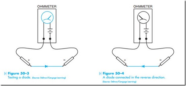
The diode can be tested with an ohmmeter. When the leads of an ohmmeter are connected to a diode, the diode should show continuity in only one direction. For example, assume that when the leads of an ohmmeter are connected to a diode, it shows continuity. If the leads are reversed, the ohm- meter should indicate an open circuit. If the diode shows continuity in both directions, it is shorted. If the ohmmeter indicates no continuity in either direction, the diode is open. To test the diode, follow this two-step procedure:
1. Connect the ohmmeter leads to the diode.
Notice if the meter indicates continuity through the diode or not, Figure 50–3.
2. Reverse the diode connection to the ohm- meter, Figure 50–4. Notice if the meter indicates continuity through the diode or not. The ohmmeter should indicate continuity through the diode in only one direction.
NOTE: If continuity is not indicated in either direction, the diode is open. If continuity is indicated in both directions, the diode is shorted.
RECTIFIERS
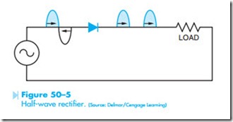
Diodes can be used to perform many jobs, but their most common use in industry is to construct a rec- tifier. A rectifier is a device that changes or converts AC voltage into DC voltage. The simplest type of rec- tifier is known as the half-wave rectifier. Refer to the circuit shown in Figure 50–5. The half-wave rectifier can be constructed with only one diode, and gets its name from the fact that it will rectify only half of the AC waveform applied to it. When the voltage applied to the anode is positive, the diode is forward biased and current can flow through the diode, load resistor, and back to the power supply. When the voltage applied to the anode becomes negative, the diode is reverse biased and no current will flow. Since the diode permits current to flow through the load in only one direction, the current is DC.
Diodes can be connected to produce full-wave rectification, which means both halves of the AC waveform will be made to flow in the same direc- tion. One type of full-wave rectifier is known as the bridge rectifier and is shown in Figure 50–6. Notice the bridge rectifier requires 4 diodes for construction.
To understand the operation of the bridge rectifier, assume that point X of the AC source is positive and point Y is negative. Current will flow to point A of the rectifier. At point A, diode D4 is reverse biased and D1 is forward biased. The current will flow through diode D1 to point B of the rectifier. At point B, diode D2 is reverse biased, so the current must flow through the load resistor to ground. The current returns through ground to point D of the rectifier. At point D, both diodes D4 and D3 are forward biased, but current will not flow from positive to positive. Therefore, the current will flow through diode D3 to point C of the bridge, and then to point Y of the AC source, which is negative at this time. Since current flowed through the load resistor during this half cycle, a voltage is developed across the resistor.
Now assume that point Y of the AC source is positive and X is negative. Current will flow from point Y to point C of the rectifier. At point C, diode
D3 is reverse biased and diode D2 is forward biased. The current will flow through diode D2 to point B of the rectifier. At point B, diode D1 is reverse biased, so the current must flow through the load resistor to ground. The current flows from ground to point D of the bridge. At point D, both diodes D3 and D4 are forward biased. As before, current will not flow from positive to positive, so the current will flow through diode D4 to point A of the bridge and then to point X, which is now negative. Since current flowed through the load resistor during this half cycle, a voltage is developed across the load resistor. Notice that the current flow was in the same direction through the resistor during both half cycles.
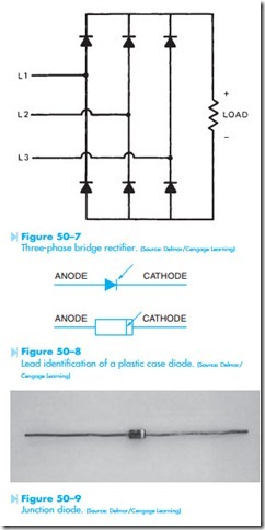
Most of industry operates on three-phase power instead of single-phase. Six diodes can be connected to form a three-phase bridge rectifier, which will change three-phase AC voltage into DC voltage. Refer to the circuit shown in Figure 50–7.


