Electrical Circuits
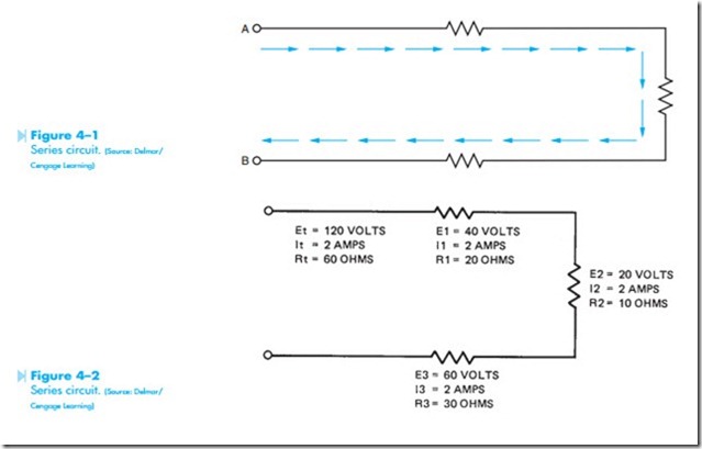
Electrical circuits can be divided into three basic types. These are series, parallel, and combination. The simplest of these circuits is the series circuit shown in Figure 4–1. A series circuit is characterized by the fact that it has only one path for current flow. If it is assumed that current must flow from point A to point B in the circuit shown in Figure 4–1, it will flow through each of the resistors. Therefore, the current flow in a series circuit must be the same at any point in the circuit. Another rule of series circuits states that the sum of the voltage drops around the circuit must equal the applied voltage. A third rule of series circuits states that the total resistance is equal to the sum of the individual resistors.
The circuit shown in Figure 4–2 shows the values of current flow, voltage drop, and resistance for each of the resistors. Notice that the total resistance of the circuit can be found by adding the
values of each of the individual resistors (20 + 10 + 30 = 60 ohms). The amount of current flow in the circuit can be found by using Ohm’s law.
There is a current flow in the circuit of 2 amps. Notice that the same current flows through each of the resistors. The voltage drop across each resistor can be found using Ohm’s law (E = I X R). The voltage dropped across resistor R1 is 2 X 20 = 40 volts. This means that it takes a voltage of 40 volts to push 2 amps of current through 20 ohms of resistance. If a voltmeter is connected across resistor R1, it would indicate a voltage drop of 40 volts. The voltage drop of resistor R2 can be found the same way (E = I X R), (2 X 10 = 20). The voltage dropped across resistor R2 is 20 volts. The third resistor has a voltage drop of 2 X 30 = 60 volts. Notice that if the voltage drops are added together, they will equal the voltage applied to the circuit (40 + 20 + 60 = 120).
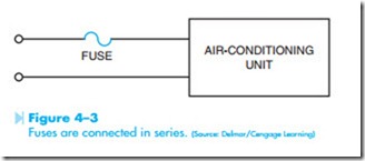
Because a series circuit has only one path for cur- rent flow, if any point in the circuit should become open, current flow throughout the entire circuit will stop. Some strings of Christmas tree lights are wired in series. If any bulb in the string burns out, all of the lights will go out. When the defective bulb is replaced, all of the lights will operate. Because of this characteristic of series circuits, fuses and circuit breakers are connected in series with what they are intended to protect. Figure 4–3 shows a fuse used to protect an air conditioning unit. If the fuse should open, current flow to the entire circuit will stop.
PARALLEL CIRCUITS
Parallel circuits are characterized by the fact that they have more than one path for current flow. The circuit shown in Figure 4–4 illustrates multiple paths of a parallel circuit. If the current in this
circuit is assumed to flow from point A to point B, there are three separate paths through which it can flow. Current can flow from point A, through resistor R1 to point B, or it can flow from point A through resistor R2 to point B, or from point A through resistor R3 to point B. Because current can flow through each of these resistors, the total cur- rent flow in the circuit is the sum of these individual currents. A rule for parallel circuits states that the total current in a parallel circuit is the sum of the cur- rents through the individual paths (It = I1 + I2 + I3). Notice in Figure 4–4 that each of the resistors is connected directly across the incoming power line. Therefore, all the components in a parallel circuit have
Each time a new component is added to a paral- lel circuit, a new path for current flow is created. Because there is less opposition to current flow each time a component is added, the total resistance of the circuit is decreased. The total resistance of a parallel circuit can be found using either of three formulas. The first of these formulas is:
The third formula can be used only when all resistors connected in parallel are the same value. Assume that four resistors with a value of 100 ohms each are connected in parallel. The total resistance would be 25 ohms. To use this formula, divide the resistance of one resistor by the total number of resistors.
Figure 4–5 shows a parallel circuit containing three resistors with the values of 15, 10, and 30 ohms. The total resistance of the circuit can be found by using either of the two formulas.
Notice that in this formula only two of the resistors can be found at a time. It is now necessary to use the total resistance of the first two resistors and use that value for R1 in the formula. Resistor R3 is used in the R2 position in the formula.
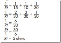
resistance by plugging the values of resistance into the formula. With these values, it becomes a matter of adding fractions. When fractions are to be added, the first thing that must be done is to find some number all the denominators will divide into. This is called finding a common denominator. For this problem, 30 will be the common denominator.
Notice that the two formulas give the same answer.
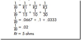
Another method of finding the total resistance in a parallel circuit is to find the reciprocal of each individual resistor. A third rule for parallel circuits states that total resistance is the reciprocal of the sum of the reciprocals of the individual resistors. The problem can, therefore, be solved by finding the reciprocal of each individual resistor, adding them together, and finding the reciprocal of the sum. (The reciprocal of any number can be found by dividing that number into 1.) The problem can be solved as follows:
If 120 volts is applied to the circuit, the values of voltage and current for the entire circuit can be found. Because each of the resistors is connected directly across the power line, each resistor will have the same voltage drop of 120 volts. The current flow through resistor R1 can be found using Ohm’s law.
The current flow through resistor R2 is (120/10 = 12 amps). The current flow through resistor R3 is (120/30 = 4 amps). The total current flow in the circuit can be found by using the formula
Notice that the total current can also be found by adding the currents flowing through the individual resistors (8 + 12 + 4 = 24 amps).
Most circuits are connected in parallel. The lights and outlets in a house are connected in parallel. Because all of the lights and outlets are connected in parallel, each light has an applied voltage of 120 volts, and each outlet can supply 120 volts to whatever is connected to it. If the lights in a house were wired in series, all of the lights would have to be turned on before any of them would burn.
COMBINATION CIRCUITS
A combination circuit contains both series and parallel connections within the same circuit. In
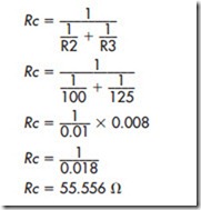
Figure 4–6, resistor R1 is connected in series with resistors R2 and R3. Resistors R2 and R3 are connected in parallel with each other. If it is assumed that current flows from point A to point B, all of the current will have to flow through resistor R1. At the junction of resistors R2 and R3, however, the determining the total resistance is to calculate the resistance of the parallel block formed by resistors R2 and R3. This value will become RC (resistance of the combination).
current divides and flows through separate paths.
The amount of current that flows through each resistor is determined by its resistance. Notice that
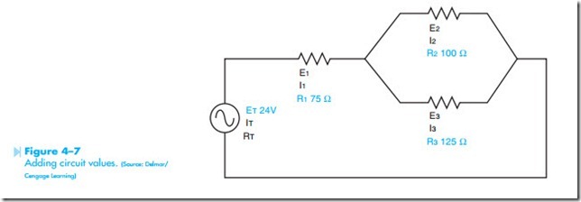
Values will now be added to the example circuit shown in Figure 4–6. It will be assumed that resistor R1 has a value of 75 ohms; resistor R2 has a value of 100 ohms; and resistor R3 has a value of 125 ohms. It will also be assumed that a voltage of 24 volts is connected to the circuit, Figure 4–7. To find the missing values in this circuit, it is first necessary to determine the total resistance. The first step in Now that the combined resistance of resistors R2 and R3 is known, this value can be treated as one single resistor. The circuit will now be redrawn as shown in Figure 4–8. The circuit is now a simple series circuit containing resistors R1 and RC.
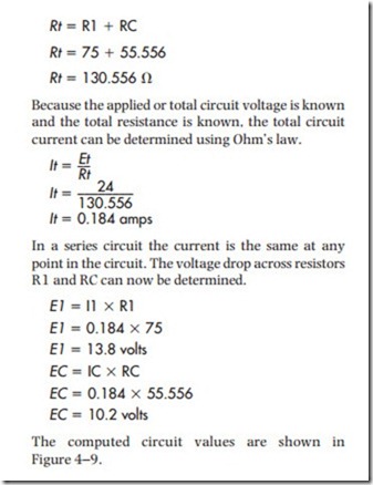
The total circuit resistance of the circuit can be determined by adding the values of resistors R1 and RC.
The computed circuit values are shown in Figure 4–9.
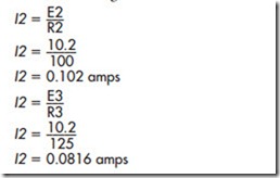
Resistor RC in reality is the combined values of resistors R2 and R3. The values that apply to resis- tor RC, therefore, apply to the parallel block formed by resistors R2 and R3. In a parallel circuit, the volt- age is the same across each branch. Therefore, the voltage dropped across resistor RC is dropped across both R2 and R3. Now that the voltage drop across each is known, the current flow through each can be determined using Ohm’s law.
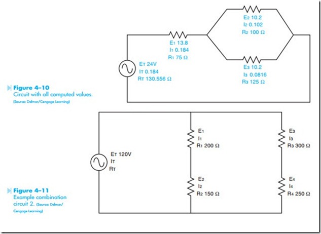
The circuit with all calculated values is shown in Figure 4–10.
Another example of a combination circuit is shown in Figure 4–11. In this circuit, resistors R1 and R2 are connected in series with each other and resistors R3 and R4 are connected in series with each other. Resistors R1 and R2 are connected in
parallel with resistors R3 and R4. It is assumed that resistor R1 has a value of 200 ohms, resistor R2 has a value of 150 ohms, resistor R3 has a value of 300 ohms, and resistor R4 has a value of 250 ohms. It is also assumed that 120 volts is applied to the circuit.
The first step in solving this circuit is to compute the total circuit resistance. This can be done by computing the total resistance of the branch containing resistors R1 and R2 and the branch containing resistors R3 and R4. Resistors R1 and R2 are connected in series. The total resistance of this branch can be computed by adding the values of resistors R1 and R2. This value will be RC1 (resistance of combination 1).
The resistance of the second branch can be computed by adding the values of R3 and R4. This resistance value will be RC2 (resistance of combination 2).
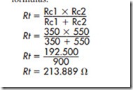
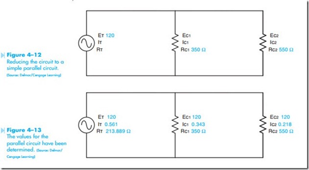
The circuit can now be reduced to a simple parallel circuit containing a 300-ohm and a 550-ohm resistor, Figure 4–12. The total resistance can now be computed using one of the parallel resistance formulas.
The total current can now be computed using Ohm’s law.
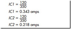
Because resistors RC1 and RC2 are connected in parallel, the voltage across each is the same as the applied voltage of the circuit. The current through each branch can now be determined.
The complete values for the parallel circuit are shown in Figure 4–13.
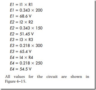
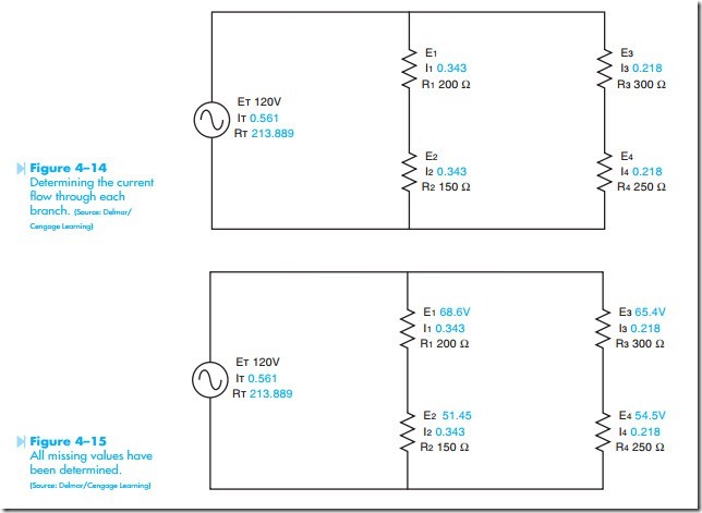
The values of RC1 and RC2 can now be substituted in the original circuit. Resistor RC1 is a combination of resistors R1 and R2. The values of RC1 apply to the branch composed of R1 and R2. Resistors R1 and R2 are connected in series. In a series circuit, the current flow is the same through any part of the circuit. Therefore, the current flowing through RC1 is the same cur- rent flowing through R1 and R2. Likewise, the current flowing through RC2 is the same current that flows through resistors R3 and R4, Figure 4–14. Now that the value of resistance and current are known for each of the resistors, the voltage drop across each can be computed.
