Heat Pump System Components
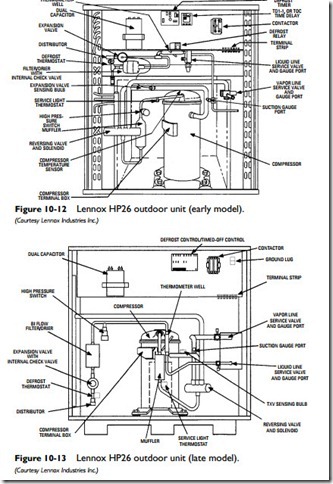
Figures 10-12 and 10-13 illustrate the components in the outdoor unit of two Lennox residential heat pumps. They can be grouped into four categories:
1. Compressor section (outdoor unit).
2. Air-handler section (indoor unit).
3. Refrigerant lines.
4. Heat pump controls.
The compressor section of a heat pump contains the compressor (or compressors), outdoor coil, fan(s) and motor(s), control system box, and reversing valve. In addition, the compressor section will also contain a refrigerant-distributing device and the defrosting controls (automatic timer and terminating thermostat). The compressor section of a remote, or split-system, heat pump is located outdoors.
The air-handler section consists of the indoor coil, blower and blower motor, check valve, thermal expansion valve, refrigerant distributing device, and the air filter(s).
The refrigerant lines are divided into a liquid line containing the refrigerant in a liquid state and a vapor or suction line containing the refrigerant vapor. During the cooling cycle, cool refrigerant vapors are moving through the line to the compressor section. During the heating cycle, hot vapors are moving in the opposite direction.
The heat pump controls include the thermostat, reversing valve, expansion/check valves, safety switches, and other components that ensure safe operation and which direct and regulate the flow of the liquid refrigerant.
Compressor
The compressor is used to receive the refrigerant vapor at low pressure and compress it into a smaller volume at higher pressure and temperature. It then pumps the refrigerant vapor to one of the coils for either the heating cycle or the cooling cycle operation.
The compressors used in residential and light-commercial construction are hermetic compressors. A hermetic compressor is so called because its components are sealed inside a welded housing. The housing (or can) contains an electric motor and a pump.
Note
A sealed (hermetic) compressor must be replaced if it fails because it cannot be repaired on-site.After it is replaced, filter dryers must be installed to remove any moisture and/or acid in the system.
Compressors can be reciprocating, scroll, rotary, disc, or screw types. The reciprocating and scroll compressors are the types used most commonly in residential and light-commercial heat pump installations. See Chapter 9 (“Air-Conditioning Equipment”) for additional information on compressors.
Indoor Coil and Blower
The indoor coil is the part of a split-system heat pump located indoors. During the cooling cycle, the indoor coil cools and dehumidifies the air by converting liquid refrigerant into a gas, which absorbs the heat from the air. The warmed refrigerant is then carried through a tube to the outdoor unit.
Note
During the cooling cycle, the heat pump draws heat from the air inside the house or building. Moisture in the air will condense on the indoor coil and must be drained to the outdoors through a condensate drain. A condensate pump should be installed to assist drainage because reliance on gravity alone will not provide efficient drainage. Do NOT allow the condensate to drain into the crawl space. Doing so will eventually result in water damage to the floor joists and other wood framing members.
During the heating cycle, heat is extracted from the outdoor air and released by the indoor coil. The heat is blown into the interior rooms and spaces by a fan, which is sometimes called an air handler or blower. Both direct-drive and belt-drive motors are used.
Outdoor Coil and Fan
The outdoor coil is the part of a split-system heat pump located outdoors in the same cabinet housing the compressor. The outdoor fan is a direct-drive unit.
Refrigerant Lines
The refrigerant lines are divided into a liquid line containing the refrigerant in a liquid state and a vapor or suction line containing the refrigerant vapor. During the cooling cycle, cool refrigerant vapors are moving through the line to the compressor section. During the heating cycle, hot vapors are moving in the opposite direction.
The lines should be reasonably straight. Any excess lines that need to be coiled should be coiled horizontally so that they don’t form an oil trap. Vertical coils may prevent needed lubricant from returning to the compressor.
Both refrigerant lines should be insulated. Reducing unwanted heat loss and heat gain through the refrigerant lines saves energy.
