Gas-Fired Pool Heaters
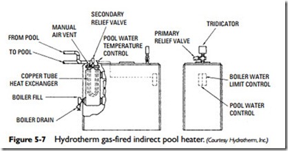
Gas-fired indirect pool heaters (see Figure 5-7) are available in the same Btu input/output ratings as the oil-fired types. They differ only in certain items of standard equipment that relate directly to
the type of fuel used. Gas-fired pool heaters will also differ accord- ing to the type of ignition system. There are two types of ignition systems used in gas-fired pool heaters:
• Millivolt (or standing pilot) ignition systems
• Automatic spark ignition systems
A millivolt ignition system is one in which the pilot light is con- tinuously burning. The heat from the pilot light is used to generate a low-voltage electrical current. The electrical current produced by the pilot light is strong enough to open and close the main gas valve (also sometimes called a combination gas valve) as well as the controls and safety devices on the heater.
Note
A pilot light that is continuously lit is sometimes called a standing pilot or standing pilot light.
An automatic spark ignition system (also sometimes called an intermittent ignition system or simply an IID system) has a pilot light that is lit only when the heater is operating. An external elec- trical source is used to spark the pilot and operate the controls and safety devices on the heater.
In addition to the pilot light, a gas-fired pool heater also will include a number of different components, safety devices, and controls. Those included in the heater will depend on the type of ignition system used as well as its make and model. They include the following:
• Pilot generator. A pilot generator (also sometimes called a thermocouple) is the device in a millivolt ignition system that converts the heat energy of the pilot flame to the electrical energy required to operate the main gas valve. Pilot genera- tors are not used in the automatic spark ignition systems.
• Control circuit. The control circuit consists of a series of safety devices used to control the flow of electricity to the main gas valve. If there is a malfunction somewhere in the heater, one or more of these safety devices in the control cir- cuit will interrupt the flow of electricity to the main gas valve and prevent the burners from operating. The devices in the control circuit include safety switches (see safety switches), a fusible link (see gas burner tray), and a remote on-off switch.
• Safety switches. A variety of different types of switches are used in gas-fired pool heaters for safety and operational control purposes.
• Pressure switch. A device that prevents the heater from starting until there is sufficient water pressure in the system.
• High-limit switch. A device that prevents the water temper- ature in the pool heater from exceeding a preset upper limit (commonly 140ºF).
• Flow switch. A device that prevents the heater from starting if there is not enough water flowing through the system.
• Fireman switch. A device that allows the circulator (pump) to continue operating up to 15 minutes after the heater has shut off. The additional pump running time allows the sys- tem to cool down.
• Bypass valve. The bypass valve is used to maintain a constant flow of water through the heat exchanger. The cool water protects the heat exchanger surfaces and other heater compo- nents from excessively high and potentially damaging temper- atures. The bypass valve and the fireman switch provide similar functions in a pool heater.
• Automatic gas valve. The automatic gas valve (also sometimes called the main gas valve or combination valve) regulates the flow of gas to the burner tray and pilot. It is controlled by the heater control circuit.
• Gas-pressure regulator. A device that regulates the gas pres- sure. It is commonly combined with the main gas valve in the same unit (hence the name combination gas valve).
• Gas shutoff valve. A valve used to shut off the supply of gas to the burners when a heater malfunction occurs.
• Thermostat. As in other heating systems, a thermostat is used to control operation within a preset temperature range. When the pool water temperature drops below a preset low-temper- ature limit setting, the thermostat switches on the pool heater. When the temperature of the pool water reaches the upper preset limit, it shuts off the pool heater.
Other gas-fired pool heater components, many of which are also found on oil-fired, electric, and solar heaters, include the following:
• Heat exchanger. A device used to transfer heat from air, fluid, or water contained in one circulating system to the air, fluid, or water contained in an adjacent one without any intermix- ing. Heat exchangers are available in the form of flat plates or fins, coils, or tubes and are made of a metal that easily absorbs heat. Copper-finned heat exchangers are the type most commonly used in pool heaters. These consist of closely spaced flat fins attached to copper tubing.
• Header. The header (also called a manifold) is the component that directs the flow of water in and out of the heat exchanger. There is a header at each end of the heat exchanger. The front header, through which the water flows into the heat exchanger, contains a flow control assembly that is used to mix the cool incoming water with the hot outgoing water as it leaves the heat exchanger through the back header. This ensures a temperature differential of 25ºF or less between the temperatures of the incoming and outgoing water. This reduced temperature differential prevents condensation, min- eral deposits, and other problems associated with excessively high temperature differentials.
• Gas burner assembly. A pool heater may have as many as 16 and as few as 6 burners, depending on the make and model. The burner tubes are arranged in a parallel array and con- nected by a manifold pipe. A pilot light is mounted on the last burner tube. The gas burner tray beneath the burners can be removed from the cabinet for cleaning.
• Pool heater aquastat. A pool heater aquastat is used to con- trol pool water temperatures and provide high-limit boiler control. The high-limit control provides shutdown protection to prevent boiler overheating. Some models are equipped with automatic reset, while others are equipped with manual.
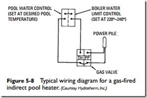
A typical wiring diagram for a gas-fired indirect pool heater is shown in Figure 5-8. The pool water control on the dual aquastat is set at the desired pool temperature. The cold water from the pool starts the boiler, which continues to produce heat until the pool water temperature reaches the setting on the pool control. When this point is reached, the boiler shuts off. The boiler water temper- ature is controlled by the water-limit control.

