Basic Components of an Oil Furnace
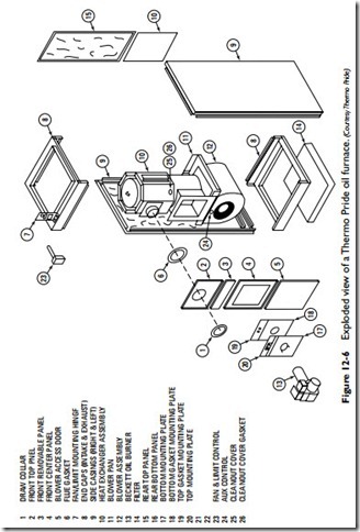
The principal components of an oil furnace are illustrated in Figure 12-6. They are listed as follows:
1. Furnace controls
2. Heat exchanger
3. Burner assembly
4. Fuel pump and motor
5. Blower and motor
6. Combustion blowers
7. Cleanout and observation ports
8. Vent openings
9. Air filter(s)
Each of these components is briefly described in the sections that follow. More detailed information is contained in Chapter 1, “Oil Burners,” and Chapter 5, “Gas and Oil Controls” of Volume 2.
Furnace Controls
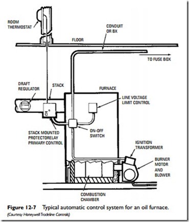
A number of different controls are used to govern the operation of
an oil furnace. Some, but not all of them, are shown in Figure 12-7.
Thermostat
A room thermostat controls the operation of the furnace. The thermostat senses air-temperature changes in the space or spaces being heated, closes an electrical circuit, and starts the ignition process. See Chapter 4, “Thermostats and Humidistats” of Volume 2 for a detailed description of thermostats.
Cad Cell
The cad cell is the principal safety device on an oil furnace. It is located inside the burner assembly in back of the burner access panel. The function of the cad cell is to prove (detect and verify) the burner flame at the start of the heating cycle. In this respect, it pro- vides the same function as the thermocouple in a gas furnace. If the cad cell cannot prove the burner flame, it opens the circuit to the burner, which shuts off the burner motor and the ignition trans- former. A detailed description of cad cells can be found in Chapter 5, “Gas and Oil Controls” in Volume 2.
Fan Controls
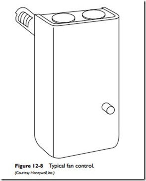
The fan and limit control is a switching and safety device commonly located in a metal box attached to the outside of the furnace
(Figure 12-8). Its function is to turn the blower on and off within a set temperature range and to shut off the burner if the furnace gets too hot.
The fan and limit control has two temperature settings: an upper one and a lower one. When the temperature in the house reaches the upper setting on the fan control, the fan control circuit opens and turns off the burner. The blower continues to run until the tem- perature in the heat exchanger reaches the lower temperature set- ting on the fan control, opens the circuit, and turns off the blower.
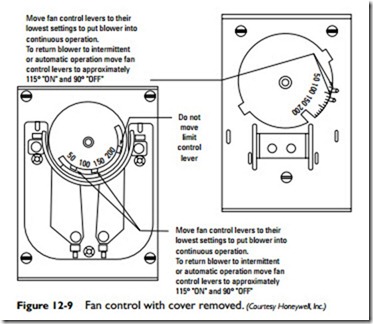
Figure 12-9 illustrates the internal components of a typical fan control box. The Fan On and Fan Off pointers on the dial are used to establish the temperature range settings. The Safety Limit control is normally set by the manufacturer and should not be adjusted. Always set the Auto/Manual Switch to Auto before reinstalling the fan control cover. A detailed description of fan and limit controls is found in Chapter 6, “Other Automatic Controls” of Volume 2.
Some modern oil furnaces are equipped with electronic fan con- trols instead of the fan and limit control switches. The control either is a separate box attached to the furnace or is an integral part of the electronic (solid-state) control board.
Delayed-Action Solenoid Valve
A delayed-action solenoid valve fitted to a conventional oil burner will prevent oil furnace spillage (see Oil Furnace Spillage in this chapter). The valve is designed to delay the flow of oil to the
combustion chamber a few seconds after the burner starts. The delay allows the burner time to establish a draft for a more complete and efficient combustion of the oil. It also eliminates sooty buildup and backdrafting.
Related posts:
Incoming search terms:
- parts of oil furnace
- what are the parts on an oil burning furnace
- Boiler System Major Components mail
- HVAC Fans and Blowers mail
- oil burner components
- oil furnace pcb p/n 1088327
- oil furnace components
- spacing on elements on a oil furnace
- basic components of tmt oil furnace
- oil furnacebasics
- Oil furnace parts show me all of the parts for a fuel oil furnace
- Oil furnaces
- oil Furnaces manufacturers
- Oil Gas Machinery mail
- operation of oil furnaces
- options for a residential oil burner
- parts of a fuel oil furnace
- parts of a oil furnace
- What are the basic components of oil
- oil furnace mail
- oil furnace componments
- access furnace riverside intrepid
- basic component of oil furnace
- component parts of an oil burning boiler setup
- Components fo a residential oil burner?
- components of an oil fired boiler diagram
- components of oil furnace
- detailed sequence of operation for an oil fired furnace
- diagram of home oil furnace
- FURNACE OIL AUTO IGNITION TEMPERATURE
- furnance oil fired burner operation amd function of parts parts
- how does an oil furnace function
- Oil burner parts and functions m
- Oil fired furnance used for emitting
- A ___ is not a component of a furnace
- what does the motor do in a oil burner


