Introduction to Direct Digital Control, DDC
As briefly mentioned earlier, small computer processors operate Direct Digital Controls, DDC. ‘Digital’ means that they operate on a series of pulses, as does the typical PC computer. In the DDC system, all the inputs and outputs remain, however, they are not processed in the controllers, but are carried out in a computer, based on instructions called the “control logic.”
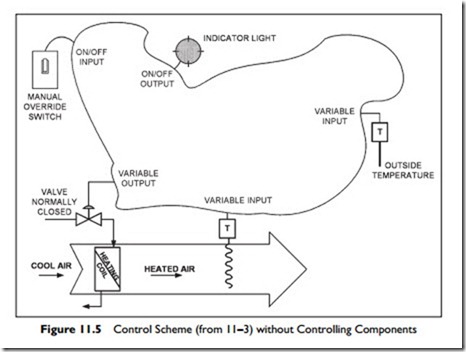
Figure 11.5, which follows, is the same control diagram that we saw in Figure 11.3, but with the controlling components, (the time clock, and the two controllers), blanked out. All the system that has been blanked out is now replaced by software activity in the computer.
In Figure 11.5, each input to or output from the DDC computer has been identified as one of the following
On/off input – manual switch
On/off output – power to light
Variable input – temperature from sensor
Variable output – power to the valve
These are the four main types of input and output in a control system. Lets consider each one briefly in terms of a DDC system.
On/off input. A switch, a relay, or another device closes, making a circuit complete. This on/off behavior has traditionally been called “digital.” Therefore in DDC terms it is generally called a “Digital Input,” or DI.
The term ‘digital’ is not considered technically correct, since there is no series of pulses, just one ‘on’ or ‘off’. Thus, for on/off points the term “Binary” is considered more correct, and the term is being encouraged in place of ‘digital’. So, “Binary Input,” BI, is the officially approved designation of an ‘on/off’ input.
On/off output. The on/off output either provides power or it does not.
The lamp is either powered, ‘on’, or not powered, ‘off’. In a similar way, this is called a “Digital Output,” DO or more correctly, binary output, BO.
Variable input. A varying signal, such as temperature, humidity or pressure, is called an “analogue” signal. In DDC terms, the input signal from an analogue, or varying, signal is called an “Analogue Input,” or AI.
Variable output. In the same way, the variable output to open or close a valve, to adjust a damper, or to change fan speeds, is an “Analogue Output,” AO.
You might think the next step is to connect these DI, DO, AI, AO points to the computer. Things are not quite that simple. A sensor that measures temperature, produces an analogue, varying signal and our computer needs a digital signal. So between each AI device and the processor there is an “A/D,” “analogue to digital,” device. These A/D devices, for AIs, are usually built in with the computer.
Similarly, for AO points there is a “D/A,” or “digital to analogue,” device that converts the digital signal to a 0–10 volts or 4–20 milliamp electrical signal. This signal has too little power to operate a valve or damper. If, for example, the controlled device is a valve that is powered by compressed air, the analogue electrical signal will go to a “transducer” in which the electrical signal will be converted to an air pressure that drives the valve. If the valve is electrically powered, the transducer will convert the low power, analogue signal to a powerful electric current.
Only standard telephone cable is required to carry the analogue electrical signal, hence the transducer is often separate from the processor and close to the controlled device. This is because it is far less effort, and cost, to run standard telephone cabling to the transducer rather than to run the air line (or electric power cable) to the processor location and back to the valve.
Naming Conventions
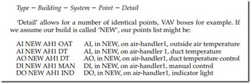
In a DDC system every input and every output must have a unique name. There are a variety of naming conventions depending on personal preference and the size and complexity of the system. Many are based on a hierarchy of elements such as
Sequence of Operations
Now look back at Figure 11.5. As we noticed earlier, the controllers and time clock are all blanked out. In a DDC system, all the actions of the controllers and time clock are carried out through software in the small computer processor. The software is a set of ordered operations, which is often called the “sequence of operation.” What do we require our software to do? The following is a very simple ‘English Language’ sequence of operations.
Do the following things:
If the time is between xx:xx a.m. and yy:yy p.m. run mode is ‘ON’, otherwise run mode is ‘OFF’
If the manual switch is closed, DI, run mode is ‘ON’
If run mode is ‘OFF’ close heating valve
If the system is in run mode ‘ON’, do the following commands Check ambient temperature, AI, and remember the value as ‘ambient’ Using ‘ambient’ lookup required setpoint from (graphic) schedule to find required air setpoint temperature. Remember this value as ‘setpoint’ Check air temperature in the duct, AI, and remember it as ‘temperature’
If ‘temperature’ is less than ‘setpoint’ increase output to valve, AO
If ‘temperature’ is greater than ‘setpoint’ decrease output to valve, AO
Go back to the beginning
These instructions are typically written into the DDC processor using a standard personal computer, PC. The programming may be a more formal version of our little example, or may use graphic symbols instead. The DDC processor can also be programmed to sound alarms, issue warnings, write messages, plot graphs, and draw graphics through the PC.
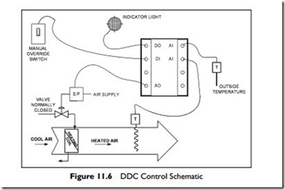
So now we can redraw Figure 11.5, to show the DDC system, Figure 11.6.
As it is shown, there is no way of accessing the processor. In a real system, there
is a communication connection providing access from a computer, typically a desktop PC or a laptop computer. The PC has many names including “the operator interface,” “front end,” or “operator machine interface” (OMI). Assuming that this panel has everything it needs to run the system, it is called a “standalone
panel.” Standalone means it has everything to keep running on its own.
A really important thing to understand is that the DDC controller can record what happens over time and either directly use that information in useful ways or provide it to the operator.
In our simple system, for example, the DDC system could check how many hours the manual switch had been on. If it had been on more than three hours, it could issue an alarm to the PC, asking the operator if it should still be in manual. This alarm could repeat every two hours to remind the operator to change back to the schedule.
In addition, there are some faults it could be programmed to detect. The heating valve is normally closed when the system is ‘OFF’. When the system starts, the duct temperature should be no hotter than the building or the outside ambient temperature. Now, our system does not know the building temperature, but we could assume it would be no higher than 80°F. Thus, we could have a software routine that checked, on startup, that the duct tempera- ture was both no higher than 5°F above ambient, and no higher than 85°F. If the duct temperature were above both these two checks, it could issue a warning that the heating valve may not be shutting off completely.
It is this ability to collect information about every point and to process it, that makes DDC so powerful. Treating it as only a controller replacement is to miss out on the real power of the system.
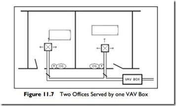
Lets consider a very simple illustration of this power of knowledge that can be written into a DDC system. We are going to consider two offices served by a single VAV box as illustrated in Figure 11.7.
The objective is to provide the occupants with conditions that are as comfortable as possible. If we connect an occupancy sensor and temperature sensor in each office, the DDC system will know if the office is occupied and the current temperature in each office. When both offices are occupied, the system can average the temperatures of the two offices and keep the average as close to setpoint as possible. Now, when the occupancy sensor detects that one of the offices is vacated, the controller can wait a few minutes to avoid annoyance and then slowly change to controlling based on just the occupied office temperature.
In addition to improving the temperature control, the occupancy sensors also allow the system to modify the amount of outside air being brought in. If one office is vacated, the outside-air volume can be reduced by the assigned volume for the empty office.
Finally, when both offices are empty, the system does not need to maintain the temperature to the same tight limits, and there is no requirement for ventilation air, so, if there is no thermal load, the VAV box can be completely closed. Similar to the example of CO2 control, in Chapter 4, Section 4.5.1, the system only provides service to occupants who are present.
There is one more advantage. The system can be designed to prevent the lights being left on for long periods when the office is unoccupied. One method is to provide power to the lighting circuits (not switch them on, just provide power) when the room is sensed as being occupied. The occupant can switch the light on and off when they like, but when they leave, it will soon go out. The system delays turning the light off for several minutes, to avoid annoyance when the occupant is only away for a few minutes.
This section has introduced you to basic ideas of DDC.
e The sensors and actuators stay, but all the control logic is in the software.
e There are four types of input and output, DO (BO), DI (BI), AO and AI.
e The complete software is a set of instructions that the DDC system can interpret and act upon.
In the next section, we are going to consider the points and sequence of operation of an air-handler. Then in Section 11.6 we will consider how DDC units can be interconnected, and can share information with each other and the operators to make a full-scale control system, rather than a collection of control loops.
Related posts:
Incoming search terms:
- direct digital control block diagram
- direct digital control system block diagram
- Ddc panel how many input and output
- ddc control schematic
- Direct digital control with block diagram
- hvac ai di bi bo
- relay ddc panel connection
- how to working di do ai ao
- soundqpp
- explain the operation of Direct Digital Control
- ACS604 DI DO AND AI AO
- DDC system with block diagram
- ddc digital input
- block diagram of ddc
- block diagram of a direct digital control
- What is the meaning of BO in DDC control


