Vapor Refrigeration/Heat Pump Cycle
The vapor refrigeration cycle is based on the inversion of the Rankine cycle. However, as we have seen in the last example, the back-work-ratio for the Rankine cycle is very small, that is only a small portion of the turbine work is required for the pump. In the inversion of the cycle the turbine becomes a compressor which consumes power. Due to the small back-work-ratio, only a very small portion of the compressor work could be regained in the inverse pump, and thus one uses a throttling valve instead.
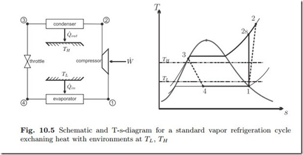
We consider a refrigerator or heat pump, exchanging heat with a cold and a warm external environment at temperatures TL, TH , respectively (recall Sec. 5.4). Heat pump and refrigerator follow the same cycle, but they differ in the external temperatures, and in the temperatures and pressures that occur in the process.
The standard vapor compression cycle operates as shown in the schematic and the T-s-diagram of Fig. 10.5: Saturated or superheated vapor at low temperature (state 1) is adiabatically compressed to higher pressure (state 2). The compressed vapor is cooled and condensed (state 3) in the condenser which exchanges heat with the high temperature environment. The liquid at state 3, either saturated or compressed, is then expanded in the throttling device to the lower pressure (state 4). In the throttling process some of the liquid evaporates, and the temperature drops. The low temperature saturated mixture at state 4 receives heat from the low temperature environment and evaporates to the compressor inlet condition (state 1).
Work and heat for the four processes are
The expense for refrigerator and heat pump is the work required to drive the compressor. The gain for the refrigerator is the heat taken in from the cold environment (qin = q41), and the gain for the heat pump is the heat rejected into the warm environment (qout = q23). Thus, depending on whether we consider a refrigeration device or a heat pump we find the coefficients of performance, as gain/expense,
Working fluids employed for vapor compression cycles must have good temperature-pressure characteristics. For the low temperatures reached, the pressures should be relatively high, and the specific volumes small, so that the pipes and the compressors must not be too voluminous. The critical point should be high, so that the process runs through the 2-phase region. Moreover, the operating temperatures must lie above the triple point, so that solid formation (freezing) will not occur. The heat of evaporation should be large. Finally, at least for household applications, one will prefer a non-toxic and non-flammable working fluid.
Water, obviously, is not suitable, due to extremely low vapor pressures at low temperatures, and the relatively high triple point temperature Ttr = 0.01 ◦C. Chlorofluorocarbons (e.g., refrigerant R12, CCl2F2) are now phased out since they destroy the ozone layer, and are presently replaced by fluorocarbons (no chlorine) like R134a (CF3CH2F). Efficient alternatives are ammonia (NH3 ) which is poisonous, and propane (C3H8) and methane (CH4) which are flammable.
Example: Vapor Compression Refrigerator
A refrigerator operating with R134a maintains the cold environment at 0 ◦C and rejects heat into an environment at 26 ◦C, the cooling power is 13 kW.
The coefficient of performance for a Carnot refrigerator operating between these temperatures is
and the Carnot refrigerator would consume a power of W˙ C = Q˙ /COPR,C = 1.24 kW.
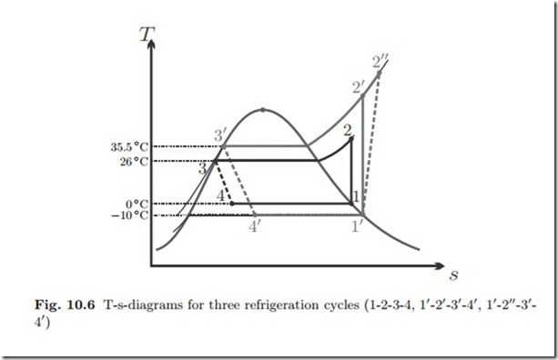
We shall study three increasingly realistic variants of the vapor refrigeration cycle and compare their performance among each other, and with the above COP of the Carnot refrigerator. For all three cycles we assume that the compressor draws saturated vapor, and the throttle draws saturated liquid.
The three cycles considered are drawn into the T-s-diagram in Fig. 10.6.
The cycle 1-2-3-4 operates without temperature difference between the cold environment and the evaporator. For the heat transfer between condenser and warm environment (2-3), there is a finite temperature difference for the cooling before the saturation temperature is reached, but the condensation occurs with infinitesimal temperature difference. Moreover, the compressor is reversible.
The cycle 11-21-31-41 operates with a temperature difference of about 10 ◦C to facilitate heat transfer between condenser and evaporator and their respective environments. Moreover, its compressor is reversible, while the cycle 11-211-31-41 has an irreversible compressor with isentropic efficiency ηC = 0.8.
We first analyze the cycle 1-2-3-4: From the tables we find the following property data for the corner points:3
This value is below the COP of the Carnot refrigerator since irreversible losses occur in the throttle and in heat transfer over finite temperature difference for the first part (before the 2-phase region is reached) of the cooling process 2-3. With the required cooling power Q˙ in = 13 kW the mass flow and power consumption are
The finite temperature difference for heat transfer reduces the COP considerably. For this process mass flow and power consumption are
This example shows explicitly how internal (throttle, compressor) and external (heat transfer over finite temperature differences) irreversibilities lead to a significant reduction of the performance characteristics of a cycle in comparison to the best possible case (here: the Carnot refrigerator).
The realistic cooling cycle 11-211-31-41 has a COP that is not much more than 1/3 of the Carnot cycle. Advanced cooling cycles use process modifications like cascade refrigeration that increase the COP (Sec. 12.5).
To understand the irreversibilities better, we determine entropy generation and work loss for the four processes in the refrigeration cycle. To compute these, we require the entropies which are
The 2nd law gives the entropy generation rates in compressor, condenser, throttle and evaporator as
As was shown in Secs. 5.4,5.10, refrigerator work loss is obtained by multiplying entropy generation with the temperature of the environment,5 W˙ loss,R = TH S˙gen , which gives the individual contributions
We see that each of the four sources of irreversibility—two internal, and two external—contributes about one quarter of the total work loss of W˙ loss,R =
2.337 kW. This result clearly shows that for a proper thermodynamic assessment of a system one must consider both, internal and external irreversibilities. Note that the work loss is the difference between the actual system work and the work of the Carnot refrigerator (apart from round-off errors).


