Insulation Principles
This chapter is not concerned with the theoretical aspects of heat loss or gain, or with heating and cooling calculations per se. These problems are discussed in considerable detail in other chapters of this book, particularly in Chapter 2 (HEATING FUNDAMENTALS), Chapter 4 (HEATING CALCULATIONS, and Chapter 9, (Volume 3) (AIR CONDITIONING CALCULATIONS). The purpose of this chapter is to describe the various types of insulation used in construction , the methods of applying insulation, and the thermal properties of various building materials.
THE NEED FOR INSULATION
An uninsulated structure, or one that is poorly insulated, will experience a heat gain in the summer (or a heat loss in the winter) as high as 50% . The exact percentage will depend upon the types of materials used in its construction, because all construction material will have some insulating effect. In any event, it has been observed that approximately 30% of heat gain (or loss) is ex perienced through ceilings and about 70% occurs through walls, glass, window and door cracks, or as a result of air ventilation.
Any attempt to heat or cool an uninsulated structure would obviously be terribly inefficient and expensive. Obviously, the possibility of anyone being so shortsighted as to attempt to install a heating or cooling system in such a structure is fairly remote, but inadequate insulation in existing structures, or the failure to provide for proper insulation in proposed construction, is a com mon occurrence. The provision for some form of barrier to reduce the rate of heat flow to an acceptable level is therefore of prime importance. Insulation materials serve this purpose with varying degrees of effectiveness. As much as 80 to 90% of heat loss (or gain) through ceilings and 60% of heat loss (or gain) through walls can be prevented by properly insulating these areas.
The inefficiency of ordinary building materials to resist the passage of heat brought about the need for the development of materials specifically designed for insulation. A good insulating material should be lightweight, contain numerous air pockets, and exhibit a high degree of resistance to heat transmission. It should also be specifically treated to resist fire and the attacks of rodents and insect. Finally, a good insulating material will react well to excess moisture by drying out and retaining its resistance to heat flow rather than disintegrating.
Many inexperienced workers seem to feel that the more insula tion one uses the better the insulating effect. Unfortunately, this does not hold true on a one-to-one basis. For example, twice as much insulation does not insulate twice as well. There is ap parently a law of diminishing returns operating here. The first layer of insulation is the most effective, with successive layers decreasing in the effectiveness to impede the rate of heat flow.
The capacity of a heating or cooling system is determined by the amount of heat that must be supplied (heating applica tions) or removed (cooling applications) to maintain the desired temperature within the structure or space. In heating applications, the amount of heat supplied to a space at constant temperature should roughly equal the amount of heat lost. In cooling applica tions, the heat removed from a space should be roughly equal to the amount of heat gained. Both heat loss and heat gain will be controlled by the way in which the structure is insulated. Good insulation will reduce the rate of heat flow through construction materials to an acceptable level, and this will mean that a heating or cooling system will be able to operate much less expensively and with greater efficiency. It will also mean that the capacity of the heating or cooling unit you wish to install will be less than the one required for a poorly insulated structure. This, in turn, will reduce the initial equipmen t and installation costs. As you can see, the type and quality of insulation in a structure is an impor tant factor to be considered when designing a heating or a cooling system.
The roof or attic floor of any structure can be insulated, as can also the walls of any frame building, whether of stucco, clapboard, shingles, brick or stone veneer. The form in which the insulation is applied depends on whether the structure is already built or is being constructed.
PRINCIPALS OF HEAT TRANSMISSION
Heat flows through a barrier of building materials (e.g. walls, ceilings, floors, etc.) by means of conduction and radiation. When it has passed to the other side of this barrier, it continues its movement away from the source by means of conduction, radia tion, and convection. The direction of heat flow depends on the relationship of outdoor and indoor temperatures, because warmer air will always move toward a colder space. Thus, in the summer months, the warmer outdoor air will move toward the cooler indoor spaces. This is referred to as heat leakage, and is described in Chapter 9, Volume 3 (AIR CONDITIONING CALCULA TIONS). In the winter months, the reverse is true. The warmer indoor air moves to the cooler outdoor spaces, and this phenom enon is referred to as heat loss (see Chapter 4. HEATING CAL COLATIONS). The purpose of insulation is to reduce the rate of heat flow to an acceptable level.
Heat Transfer Values
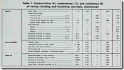
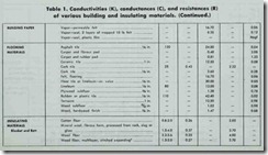
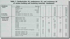
The American Society of Heating, Refrigerating and Air Con ditioning Engineers (ASHRAE) has conducted considerable re search into the thermal properties of building materials and this data is used in the calculation of heat loss and heat gain. Tables of computed values for many types of construction materials and combinations of construction materials are made available through ASHRAE publications. One type of table gives the design values
(i.e. conductivity values, conductance values, and resistance values) of various building and insulating materials. These values are used to calculate the coefficients of heat transmission (U values) for different types of construction (e.g. masonry walls,
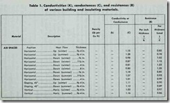
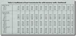
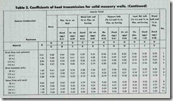
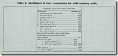
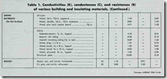
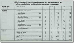
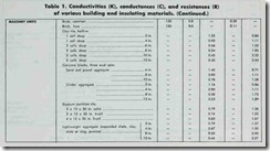
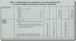
frame partitions, etc.). Examples of these two types of tables have been taken from the 1960 ASHRAE Guide (see Table 1 and Table 2).
The four heat transfer values contained in these tables are:
(1) the k-value (thermal conductivity); (2) the C-value (thermal conductance); ( 3) the R-value (thermal resistance); and ( 4) the U-value (overall coefficient of heat transmission). Each of these heat transfer values will be examined before their use in heating and cooling calculations is explained.
Thermal Conductivity
The k-value (thermal conductivity) represents the amount of heat which flows through one square foot of a homogeneous material one inch thick in one hour for each degree of tempera ture difference between the inside and the outside temperatures.
To illustrate, let’s use an example from the ASHRAE data shown in Tables 1 and 2. You will note that the k-value for face brick listed in Table 1 is 9.0. In other words, 9.0 Btu’s of heat pass through a square foot of one-inch thick face brick each hour. The thermal resistance (R-value) of this same one-inch thick face brick is the reciprocal of its k-value.
R = 1/k = 1/9 = 0.11
Remember, this is the thermal resistance for a one-inch thick ness of face brick. Because the masonry wall in Table 2 contains a four-inch thickness of face brick , you will have to multiply the R-value (0.11) of the one-inch thick face brick by four (i.e. four inches) to obtain the R-value (0.44) for the larger four-inch section.
Thermal Conductance
The C-value (thermal conductance) represents the amount of heat flow through a square foot of material per hour per degree of temperature difference between the inside and the outside temperatures. The C-value is based on the stated construction or thickness of the material. This distinguishes it from the k-value, which is based on a one inch thickness of a homogeneous material having no fixed thickness. For example, under “loose fill” in Table 1, you will see vermiculite listed and given a k-value of 1.48. Why a k-value? It is given a k-value (rather than a C value) because vermiculite is a loose fill-type insulating material that can be poured into a space to form whatever thickness is desired. It is convenient, then, to give numerical values (k-values) based on one inch thicknesses of these types of materials. If, say, vermiculite was used to insulate the top floor ceiling (that is to say, the attic floor) and poured to a depth of four inches, the R-value (thermal resistance) would be calculated as follows:
(1) k-value = 0.48
(2) R-value = 1/0.48 = 2.08 (1 inch)
(3) R-value = 2.08 X 4 = 8.32 (4inches)
Under “masonry units” in Table 1, you will find hollow clay tile listed with six different stated thicknesses (e.g. “1 cell deep, 3 in.; I cell deep, 4 in.; etc.”) . Each is given a C-value, rather than a k-value, because the thickness of the material listed in the table is the same thickness that will be used in the construction of a structural section.
The masonry wall in Table 2 also contains gypsum plaster
(sand aggregate) one-half inch thick. The C-value is given as 11.10, and its R-value as 0.09 (Table I). In other words, the R-value (thermal resistance) is calculated as follows:
R = 1/C = 1/11.10 = 0.09
Examine the date in Table 1 once more. You will probably note that each building material has either a k-value or a C-value, but not both. Each material is offered on the basis of either a stated thickness or an arbitrary one-inch thickness. This was explained above. Note also that each type of building material has an R-value determined by either of the following two equations:
(1) R = 1/k
(2) R = 1/C
The R-value is simply the reciprocal of either the k-value or the C-value.
Thermal Resistance
The R-value (thermal resistance) of a building material is its resistance to the flow of heat. As explained above, the R-value is the reciprocal of the k-value or the C-value, and represents heat flow resistance expressed as a numerical value.
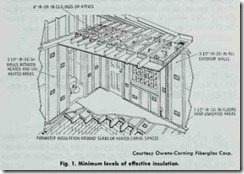
The higher the R-value of a material (or a combination of materials) the greater its resistance to the flow of heat. Ceilings should have an R-value of R-19 or better. Floors and walls should be insulated to at least R-11 (Fig. 1).
Returning to the masonry wall illustrated in Table 2, you will note that all seven R-values have been added to produce the total resistance of a solid masonry wall (i.e. 3.47). In other words, the total resistance to heat flow through a solid masonry wall of the same type of construction illustrated in Table 2 is equal to the sum of the resistances of the wall components, or:
Rt = R1 + R2 + R3 …….Rn
The total resistance (Rt) of a particular type of construction is used to determine its U-value, which represents the total insu lating effect of a structural section. The U-value is the reciprocal of the total resistance (Rt). Using the data supplied for the ma sonry wall illustrated in Table 2, its U-value is determined as follows:
U = 1/R = 1/3.47 = 0.29
Overall Coefficient of Heat Transmission
The U-value or U-factor (overall coefficient of heat transmis sion) represents the amount of heat (in BTU’s) that will pass through one square foot of a structural section per hour per de gree Fahrenheit. This is the difference between air on the inside and the air on the outside of the section. The U-value is the re ciprocal of the sum of the thermal resistance values (R-values) of each element of the structural section. The total resistance (Rt) for the solid masonry wall illustrated in Table 2 is 3.47. Since the U-value is the reciprocal of Rh the following is obtained:
U = 1/Rt = 1/3.47 = 0.29
The overall coefficient of heat transmission (U-value or U-factor) is used in the formula for calculating heat loss or heat gain. The use of this formula is described in Chapter 4 (HEAT lNG CALCULATIONS) and Chapter 9, Volume 3 (AIR CON DITIONING CALCULATIONS).
