Analog Sensing for Programmable Controllers
Many of the programmable controllers found in industry are designed to accept analog as well as digital inputs. Analog means continuously varying. These inputs are designed to sense voltage, current, speed, pressure, proximity, temperature, and so on. When an analog input is used, such as a thermo- couple for measuring temperature, a special module that mounts on the I/O rack is used. These types of sensors are often used with set point detectors that can be used to trigger alarms and turn on or off certain processes. For example, the voltage produced by a thermocouple will increase with a change of temperature. Assume that you want to sound an alarm if the temperature of an object reaches a certain level. The detector is preset with a particular voltage. As the temperature of the thermocouple increases, its output voltage increases also. When the voltage of the thermocouple becomes greater than the preset voltage, an alarm sounds.
INSTALLATION
Most analog sensors can produce only very weak signals. Zero to 10 volts or 4 to 20 milliamps is common. In an industrial environment where intense magnetic fields and large voltage spikes abound, it is easy to lose the input signal amid the electrical noise. For this reason, special precautions should be taken when installing the signal wiring between the sensor and input module. These precautions are particularly important when using analog inputs, but they should be followed when using digital inputs also.
KEEP WIRE RUNS SHORT
Try to keep wire runs as short as possible. The longer a wire run is, the more surface area of wire there is to pick up stray electrical noise.
PLAN THE ROUTE OF THE SIGNAL CABLE
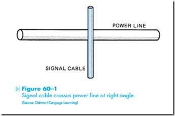
Before starting, plan how the signal cable should be installed. Never run signal wire in the same conduit with power wiring. Try to run signal wiring as far away from power wiring as possible. When it is necessary to cross power wiring, install the signal cable so that it crosses at a right angle as shown in Figure 60–1.
USE SHIELDED CABLE
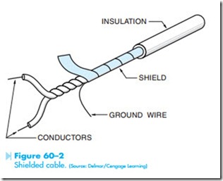
Shielded cable is generally used for the installation of signal wiring. One of the most common types, Figure 60–2, uses twisted wires with a Mylar foil shield. The ground wire must be grounded if the shielding is to operate properly. This type of shielded cable can provide a noise reduction ratio of about 30,000:1.
Another type of signal cable uses a twisted pair of signal wires surrounded by a braided shield. This type of cable provides a noise reduction of about 300:1.
Common coaxial cable should be avoided. This cable consists of a single conductor surrounded by a braided shield. This type of cable offers very poor noise reduction.
GROUNDING
Ground is generally thought of as being electri- cally neutral or zero at all points. This may not be the case in practical application, however. It is not uncommon to find different pieces of equipment that have ground levels that are several volts apart, Figure 60–3.
One method that is sometimes used to overcome this problem is to use large cable to tie the two pieces of equipment together. This forces them to exist at the same potential. This method is sometimes referred to as the brute force method.
Where the brute force method is not practical, the shield of the signal cable is grounded at only one end. The preferred method is generally to ground the shield at the sensor.
THE DIFFERENTIAL AMPLIFIER
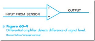
An electronic device that is often used to help over- come the problem of induced noise is the differential amplifier shown in Figure 60–4. This device detects the voltage difference between the pair of signal wires and amplifies this difference. Because the induced noise level should be the same in both conductors, the amplifier will ignore the noise. For example, assume an analog sensor is producing a 50 millivolt signal. This signal is applied to the input module, but induced noise is at a level of 5 volts. In this case the noise level is 100 times greater than the signal level. The induced noise level, however, is the same for both of the input conductors. The differential amplifier, therefore, ignores the 5-volt noise and amplifies only the voltage difference which is the 50 millivolts.


