Float and Thermostatic Traps
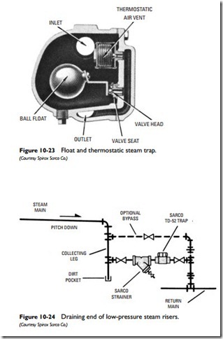
A float and thermostatic trap (see Figure 10-23) has both a thermo- static element to release air and a float element to release the con- densation. As such, it combines features of both the float trap and the thermostatic trap.
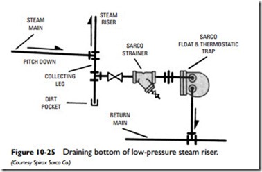
These traps are recommended for installations in which the vol- ume of condensation is too large for an ordinary thermostatic trap to handle. Float and thermostatic traps are also used in low-pressure steam heating systems to drain the bottom and end of steam risers (see Figures 10-24 and 10-25). Other applications include the draining of condensation from unit heaters, preheat and reheat coils in air conditioning systems, steam-to-water heat exchangers, blast coils, and similar types of process equipment.
Note
Check the trap-seat pressure before installation to make sure its rating is equal to or greater than the steam supply of the boiler.
If the trap is operating properly, it will immediately and continuously discharge condensation, air, and noncondensable gases from the system that enter the inlet orifice of the trap.
No Heat or Uneven Heat
Float and thermostatic traps are used in two-pipe steam heating systems to pass air and condensate into the return piping while simultaneously preventing the steam from moving past the radiators and ends of the steam mains. Failure of these traps results in the following problems:
• Trap fails in the open position causing the steam to pass into the return lines.As a result, the pressure in both the return and supply piping is the same and, without a pressure differential between the two, the steam cannot move to the radiators.
• Trap fails in the closed position, blocking the entry of air and steam into the radiators.
The condensation is handled by the ball float, which is con- nected by a level assembly to the main valve head. Condensation entering through the trap inlet causes the ball float to rise, moving the level assembly and opening the valve for discharge.
Air and noncondensable gases are discharged through the thermo- static air vent. The thermostatic element is also designed to prevent the flow of steam around the float valve.
Float and thermostatic traps operate under pressures ranging from vacuum to a maximum pressure of 200 psig; however, the great majority of them are designed for 40 psig or less.
These traps have limited resistance to water hammer. They are also vulnerable to corrosive elements in the condensation unless fitted with anticorrosive internal components.

