Steam Turbine: Rankine Cycle
About 70-75% of the World’s electrical energy are produced in steam cycles. An external heat source is used to evaporate pressurized water, and then the high pressure vapor is expanded in steam turbines. The fuel for most steam power plants is coal, followed by nuclear power. Since the heat is supplied externally, many other heat sources can be used, including oil, gas and heat from solar radiation.
The Rankine cycle, which we shall discuss now, has been the basic steam cycle for power generation, it is named after William Rankine (1820-1872). Modern steam power plants use more efficient variations of the Rankine cycle that will be discussed in Sec. 12.2.
Figure 10.1 shows a schematic of the Rankine cycle. Saturated liquid water is pressurized in an adiabatic pump (1-2). In the steam generator, the high pressure water is heated, evaporated and superheated (2-3). The superheated steam is expanded in the steam turbine (3-4), which generates work;
part of the turbine work is used to run the pump, the net work is delivered to the generator. The turbine discharges into the condenser (4-1), in which the steam is condensed back to the initial state. Pump and turbine may be irreversible. Figure 10.2 shows the Rankine cycle in the diagrams with respect to saturation lines. Work and heat for the four processes are (see Sec. 9.13)
and the heat supply is
In early steam engines the steam was expanded in piston-cylinder devices, not in turbines. Reciprocating piston engines have large load changes, and are more bulky, while turbines are running at constant loads, and can deliver the same amount of power with a significantly smaller footprint.
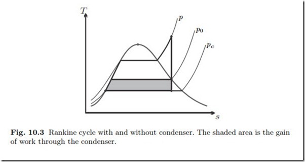
The condenser is James Watt’s (1736-1819) most important contribution— of many—to the improvement of steam engines. The temperature Tc in the condenser is prescribed through heat exchange with the environment, so that Tc is not much above the environmental temperature T0. The condenser pressure is the corresponding saturation pressure psat (Tc) which lies substantially below the environmental pressure p0. Since the work delivered by a turbine grows with the pressure ratio,1 a steam cycle with a condenser will have a significantly larger work output than a cycle that discharges into the environment. The gain of work through the condenser is illustrated in the T-s- diagram of Fig. 10.3.
A condenser requires a significant amount of cooling which usually is pro- vided by a cooling water cycle that employs cooling towers. Due to the difficulty of providing sufficient cooling, most steam locomotives do not have condensers, and discharge into the environment. Therefore steam locomotives have low thermal efficiencies, and must be supplied with fresh water frequently.2 In a steam power plant with condenser the working fluid runs continuously through the system in a closed loop, which allows the use of purified water to reduce pipe corrosion. Some of the cooling water, however, evaporates in the open cooling towers from which warm moist air rises. As the rising moist air cools down by heat exchange with the surrounding air, some of the water condenses to clouds (Sec. 19.9).
Would the pump be fed with saturated liquid-vapor mix, the sudden col-lapse of vapor bubbles during the compression process (cavitation) would induce shock waves that lead to material damage and, ultimately, pump failure.
Cooling into the compressed liquid region only increases the heat removal, and has no benefit. Thus, the pump should be fed with saturated liquid.
As the steam expands in the turbine, it crosses the saturation line and small liquid droplets form. These droplets hit the fast rotating turbine blades and cause corrosion. On the other hand, a smaller quality x4 reduces the amount of heat rejected in the condenser, and thus improves thermal efficiency. To obtain a good balance between efficiency and prevention of corrosion, one aims at having the quality at the turbine exit at x4 = 0.9 or higher.
The pipes of the steam generator are normally made from standard steel.
At the high pressures that occur in the cycle, the temperature for the pipes should not exceed ∼ 560 ◦C.
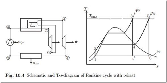
Increase of the pressure in the steam generator improves efficiency since the average temperature for heat supply increases. However, when the pressure becomes large, and the turbine inlet temperature is capped at Tmax, the expansion into the condenser leads to low qualities, and thus damage of the turbine blades due to droplet formation. This is illustrated in Fig. 10.4, where the standard Rankine cycle has the corner points 1-2-3-4’. To shift the point 4’ towards values of higher quality requires either a turbine inlet temperature T3 above the maximum temperature Tmax for the steam generator, or lower pressure p3. Another alternative, as illustrated in the figure, is to expand the steam in a first turbine to the intermediate pressure p5, reheat back to Tmax, and then expand in a low pressure turbine to the condenser pressure pc. Net work, heat in and thermal efficiency for the reheat cycle are
More complex steam cycles involve multiple turbine stages, and internal heat regeneration to improve efficiency (Sec. 12.2).
Example: Rankine Cycle
As an example we consider a standard Rankine cycle with specifications based on the discussion in the previous section: The condenser temperature is T1 = 40 ◦C, the upper pressure is p2 = p3 = 80 bar, pump and turbine are
irreversible with isentropic efficiencies ηP = 0.85 and ηT = 0.88, respectively, and the quality at the turbine exit is x4 = 0.9. Schematic and thermodynamic diagrams for this cycle are as in Figs. 10.1 and 10.2.
We begin with the computation for the pump. State 1 is saturated liquid at T1 with the properties
We have to find the corresponding turbine inlet state, for which the pressure p3 = 8 MPa is known, but not the temperature. For the solution we use a trial and error strategy: In the first step, we try T (a) = 550 ◦C, for which enthalpy and entropy are
The last value lies above the target value of h4 = 2333.6 kJ , and thus the actual temperature T3 lies between the two guesses (550 ◦C,600 ◦C). Linear
Although some small inaccuracy can be expected due to interpolation, the enthalpy h4 is at the target value.
With this, all four enthalpy values are determined, and we can compute the net work, the heat in, and the thermal efficiency of the cycle 1-2-3-4 as
Less than one percent of the turbine work is required for the pump. To understand the low back-work-ratio we recall that for a reversible adiabatic process the work for both, pump and turbine, is given by w = − { vdp. The overall pressure difference for both devices are the same, but the volumes for both processes differ considerably: The pump is fed with liquid water, while the turbine is fed with vapor which has a substantially larger volume than the liquid.
Related posts:
Incoming search terms:
- open rankine cycle
- a steam power plant machines is it an open system or close system
- steam turbine hangzhou mail
- steam turbine is close system
- steam turbine is open ayatem or close
- steam turbine is open system or close system
- steam turbine open or closed system
- steam turbines are open system
- stream turbines open and close
- turbine is open system or closed system
- what is open and close system in steam power plant
- what rankine cycle is a open cycle
- rankine cycle with closed water system
- rankine cycle is open or closed system
- rankine cycle componentan open or closed system
- a steam turbine is open or closed system
- basic process of steam ni open system
- explain why steam engine is open system
- Gas Turbine Steam Turbine Boiler Engines Wind Turbines mail
- hvac of rankine cycle
- is a steam powe plant an open system
- open rankine
- open steam rankine cycle
- open steam turbine cycle
- rankine cycle closed or open
- working of open rankine cycle


